English
 Español
 русский
 日本語
日本語
 عربى
عربى


Content
- 1 What Is Chamfered Edge Concrete and Why It Matters
- 2 How Chamfered Edges Are Formed in Concrete
- 3 Magnetic Chamfer Strips: The Professional Standard for Steel Formwork
- 4 Comparing Chamfer Strip Types: A Practical Overview
- 5 Standard Chamfer Sizes and When to Use Each
- 6 Installing Chamfer Strips Correctly: Common Mistakes and How to Avoid Them
- 7 Applications in Precast Concrete Manufacturing
- 8 Chamfered Edges and Concrete Durability
- 9 Selecting the Right Magnetic Chamfer Strip for Your Project
- 10 Chamfered Edge Concrete in Architectural and Design Contexts
- 11 Maintenance and Reuse of Magnetic Chamfer Strips
- 12 Cost Analysis: Magnetic Chamfer Strips vs Traditional Methods
- 13 Code and Specification Requirements for Chamfered Edges
What Is Chamfered Edge Concrete and Why It Matters
Chamfered edge concrete refers to concrete elements — walls, columns, slabs, beams, and precast panels — where the sharp 90-degree corner has been replaced with an angled or beveled face, typically cut at 45 degrees. The result is a clean diagonal surface running along the length of the edge. This is not purely cosmetic. A chamfered edge reduces stress concentration at corners by up to 30% compared to square edges, which means fewer chips, cracks, and spalled corners over the structure's service life.
Beyond structural performance, chamfered edges serve a critical safety function. Exposed square concrete corners are notorious for causing cuts and abrasions — a genuine hazard in warehouses, parking structures, public buildings, and infrastructure projects. A beveled corner blunts that risk immediately. In architectural work, the angled reveal also creates shadow lines that add visual depth and sophistication to an otherwise flat surface.
The most common chamfer size in general construction is a 20mm × 20mm (¾ inch) 45-degree bevel, though architectural projects frequently use 10mm, 15mm, 25mm, or custom profiles. Precast concrete manufacturers often specify deeper chamfers — 30mm or 40mm — to create stronger visual articulation between panels.
How Chamfered Edges Are Formed in Concrete
There are two fundamental approaches to creating a chamfered edge on concrete: forming the bevel before the pour using chamfer strips placed inside the formwork, or cutting and grinding the bevel after the concrete has cured. Pre-pour forming is by far the more common and cost-effective method in professional construction.
Pre-Pour Chamfer Strips
Chamfer strips — also called chamfer inserts or edge inserts — are triangular-profile pieces of material fixed inside the formwork at corners before concrete is poured. When the forms are stripped, the strip pulls away to reveal a perfectly beveled edge. This method requires no secondary operations and adds minimal time to the forming process.
The three most common chamfer strip materials are foam (polyurethane or polyethylene), PVC/plastic, and rubber. Each has its own performance profile. Foam strips are inexpensive and flexible but prone to tearing during form removal, leaving fragments bonded to the concrete surface that must be picked out by hand — a time-consuming defect-correction process. PVC strips are more durable but require mechanical fastening with nails, screws, or adhesive, which adds labor and leaves fastener holes in the formwork face.
Post-Pour Cutting and Grinding
When a chamfer is required on cured concrete that was not formed with a chamfer strip, contractors use angle grinders fitted with diamond grinding wheels or concrete routers with chamfering bits. This approach is significantly more expensive — equipment cost, labor time, and dust management all add up. A 15-meter run of chamfered edge formed during pour costs roughly 60–70% less than the equivalent edge produced by post-cure grinding. Post-pour methods are typically reserved for renovation work or correction of forming errors.

Magnetic Chamfer Strips: The Professional Standard for Steel Formwork
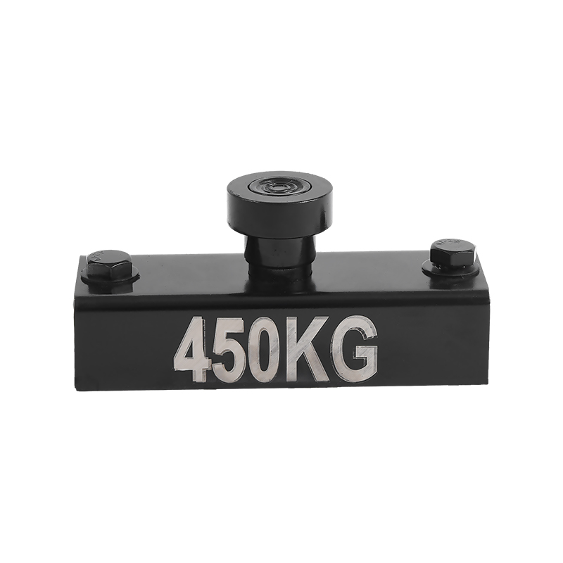
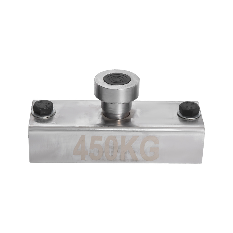
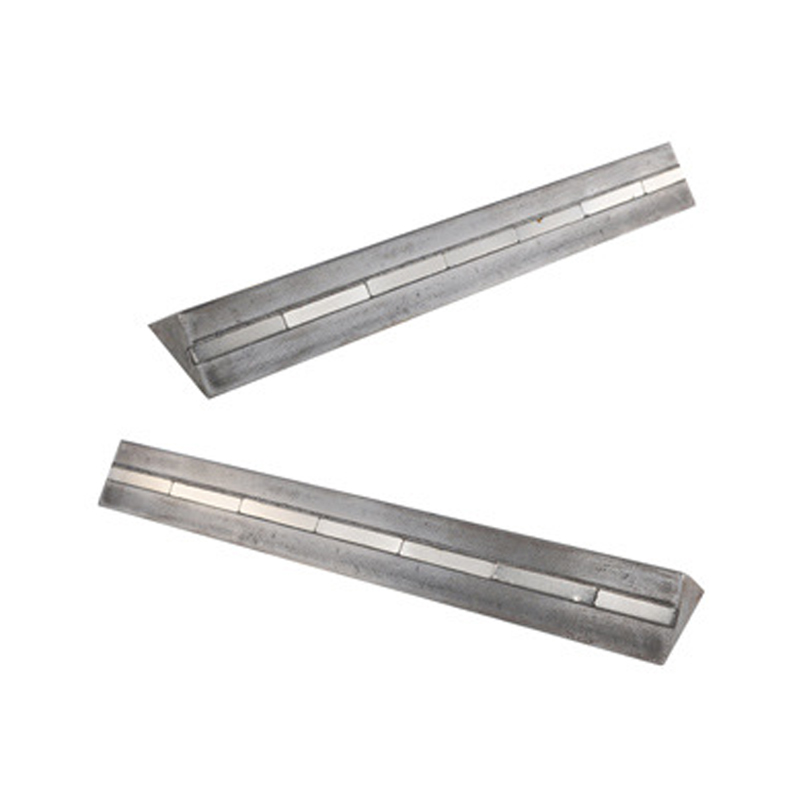
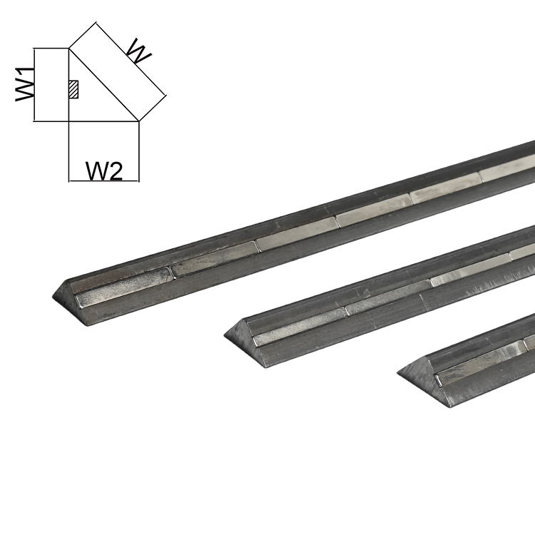
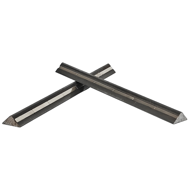
In precast concrete production and in-situ work using steel formwork, magnetic chamfer strips have become the dominant fastening solution. A magnetic chamfer strip is a triangular chamfer insert with a continuous ferrite or neodymium magnet embedded along its base. The magnet holds the strip firmly against the steel form face without any screws, nails, clips, or adhesive. Positioning takes seconds. Repositioning is equally fast.
Magnetic chamfer strips are reusable across hundreds of casting cycles, which makes their higher unit cost irrelevant when calculated on a per-use basis. A quality magnetic chamfer strip in PVC or rubber costs three to five times more than a single-use foam strip, but if it survives 300 pours — a reasonable figure for a well-maintained strip — the per-pour cost is a fraction of the disposable alternative.
How Magnetic Chamfer Strips Work
The body of a magnetic chamfer strip is typically made from rigid PVC, flexible rubber, or a combination of both. The triangular profile sits in the corner of the steel form, and the flat base face contacts the steel surface. Embedded magnets — usually spaced at 50mm to 150mm intervals along the strip — generate a holding force that resists both lateral displacement during concrete vibration and vertical movement during pour. Most manufacturers produce strips in standard lengths of 1000mm, 1500mm, and 2000mm, with joints butted together for longer runs.
The magnet specification matters. Ferrite magnets are cost-effective and work well in standard production environments. Neodymium (rare earth) magnets provide significantly stronger hold — important when the chamfer strip is positioned on vertical or overhead form faces, or when concrete is placed with high-energy internal vibrators that create substantial lateral pressure on formwork inserts.
Surface Finish Quality
One of the clearest advantages of magnetic chamfer strips over foam equivalents is surface finish quality. Foam absorbs moisture and can leave a rough, porous texture on the chamfered face. PVC and rubber magnetic strips produce a dense, smooth finish on the bevel that matches or exceeds the finish quality of the adjacent formed face. For architectural concrete — where surface blemish is unacceptable — this distinction is decisive.
Comparing Chamfer Strip Types: A Practical Overview
Choosing the right chamfer strip depends on formwork type, project scale, required reuse cycles, and finish specification. The table below summarizes the key trade-offs.
| Type | Fastening Method | Formwork Compatibility | Reuse Cycles | Surface Finish | Typical Cost |
|---|---|---|---|---|---|
| Foam Strip | Adhesive / nails | Timber, plywood | 1–3 | Fair (porous) | Very low |
| PVC Strip (nailed) | Nails / screws | Timber, plywood | 10–30 | Good | Low–medium |
| Rubber Strip | Adhesive / clips | Steel, timber | 50–150 | Very good | Medium |
| Magnetic Chamfer Strip (PVC) | Embedded magnet | Steel only | 200–500+ | Excellent | Medium–high |
| Magnetic Chamfer Strip (rubber) | Embedded magnet | Steel only | 300–600+ | Excellent | High |
Standard Chamfer Sizes and When to Use Each
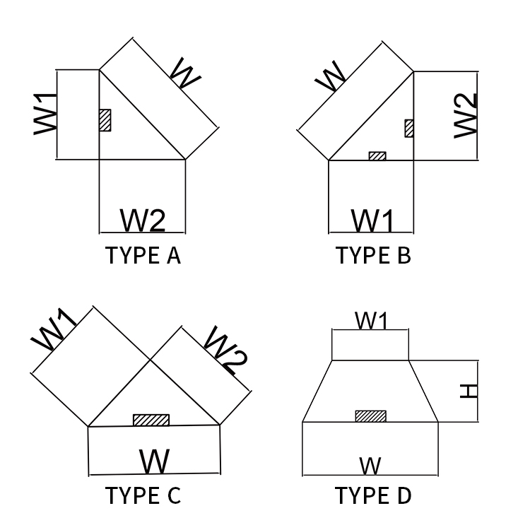
Chamfer dimensions are specified as the leg length of the right-angled triangle cross-section. A "20mm chamfer" means both legs of the triangle are 20mm, producing a 28mm diagonal face at 45 degrees. Here is how size selection typically maps to application type:
- 10mm × 10mm: Light-duty residential work, internal corners on walls and columns where minimal reveal is desired. Often used in housing construction to reduce chipping risk without an obvious visual bevel.
- 15mm × 15mm: General commercial construction standard for columns, beams, and wall edges in office and retail projects. Balances visibility and practicality.
- 20mm × 20mm: The most widely used size in civil and structural concrete. Applied to bridge abutments, retaining walls, industrial floors, and precast elements. The 20mm chamfer is the default specified size in most national concrete codes when no specific size is given.
- 25mm × 25mm: Infrastructure work including tunnels, underpasses, and heavy civil where edges are subject to impact loading from vehicles or machinery.
- 30mm × 30mm and above: Architectural precast facades, exposed aggregate panels, and signature structural elements where the shadow line is an intentional design feature. Also used in aggressive environments (marine, chemical exposure) where a larger chamfer moves the corner away from the zone of maximum deterioration.
Non-standard profiles also exist. Some precast manufacturers use a 1:2 or 1:3 ratio chamfer (a shallow bevel rather than 45 degrees) to create a different shadow line effect. Magnetic chamfer strips are available in these custom profiles from specialty formwork suppliers, though lead times and minimum order quantities apply.
Installing Chamfer Strips Correctly: Common Mistakes and How to Avoid Them
Incorrect installation of chamfer strips is one of the leading causes of edge defects in formed concrete. The resulting repairs — grinding, patching, epoxy filling — cost far more in time and materials than getting the installation right in the first place. The following are the most frequent errors seen on site.
Gap Between Strip and Form Face
Even a 1–2mm gap between the base of the chamfer strip and the form face allows cement paste to bleed underneath during vibration. The result is a fin of hardened paste along the edge of the chamfer that must be chipped away — damaging the fresh concrete in the process. For magnetic chamfer strips, this gap is typically caused by a magnet that has lost holding strength or debris between the strip and the steel form. Clean the form face with a wire brush before placing strips, and check that each section snaps firmly against the steel with no rocking.
Misaligned Joints Between Strip Sections
Where two chamfer strip sections meet end-to-end, any offset — even 0.5mm — creates a visible step in the finished chamfered edge. For magnetic chamfer strips, butting the ends together is straightforward because the magnets hold position without drift. For nailed PVC strips, joint alignment requires more care. Use a straight edge when positioning sections, and apply a small piece of tape across the joint before pouring to prevent paste infiltration.
Insufficient Release Agent
Chamfer strips — particularly PVC and rubber types — must be coated with mold release oil before each pour. Skipping this step means the strip bonds to the concrete surface and tears away chunks of the chamfer face during stripping. Apply a thin, even coat of release agent to the chamfer strip face using a brush or roller, not a spray gun — spray application tends to miss internal corners and leave pools on horizontal surfaces that cause surface blemishes.
Strip Displacement During Vibration
Internal concrete vibrators create significant lateral pressure on anything in the formwork. Foam strips held only by adhesive can migrate several millimeters during vibration, producing a wavy or misaligned chamfer. Magnetic chamfer strips resist this displacement effectively when the magnet holding force is matched to the form orientation and vibrator output. For high-frequency vibration (above 12,000 rpm), neodymium magnetic strips are preferable over ferrite magnetic strips, which may not provide sufficient holding force on vertical faces.
Applications in Precast Concrete Manufacturing
Precast concrete production is where magnetic chamfer strips are most heavily used. Precast facilities typically operate steel pallet or table forms that are reconfigured multiple times daily. In this environment, the speed and ease of repositioning magnetic chamfer strips translates directly into production throughput. A crew that previously spent 20 minutes nailing foam chamfer strips per mold can place and position magnetic chamfer strips for the same mold in under 5 minutes.
Precast elements that routinely incorporate chamfered edges include:
- Columns and column bases for multi-storey structures
- Wall panels for residential, commercial, and industrial buildings
- Staircase stringers and individual stair treads
- Bridge beams (I-beams, U-beams, box girders)
- Tunnel lining segments where chamfered edges aid ring assembly and gasket seating
- Retaining wall blocks and noise barrier panels
- Architectural cladding panels where the shadow line is a design element
In tunnel segment production specifically, chamfered edges serve a structural purpose beyond aesthetics. The chamfer creates a recessed groove when two segments are placed adjacent to one another, and this groove can be filled with caulk or grout to provide a secondary water seal. Most tunnel segment specifications require a minimum 20mm × 20mm chamfer on all longitudinal and circumferential joints for exactly this reason.
Chamfered Edges and Concrete Durability
The durability argument for chamfered edges is well supported by practical observation and materials science. Sharp 90-degree concrete corners are inherently vulnerable because the concrete at the very apex of the corner is supported on only two faces rather than three. When subjected to impact, thermal cycling, or reinforcement corrosion, this poorly supported corner tends to spall first.
Thermal cycling is particularly aggressive at exposed corners. Concrete expands and contracts with temperature change. The corner is the point where two surfaces meet at maximum exposure angle, creating bidirectional thermal stress. Over years of outdoor exposure, this cyclic stress causes microcracking that progresses to visible spalling. Studies of parking structure columns show that chamfered edges reduce the incidence of corner spalling by 40–60% over a 20-year service period compared to equivalent sharp-edged columns in the same environment.
In reinforced concrete, the cover depth at a sharp corner is geometrically less than the nominal cover measured perpendicular to a flat face. A 30mm cover on a flat wall face may reduce to effectively 21mm at a square corner when measured to the nearest rebar. Chamfering the corner physically moves the exposed surface away from the rebar, restoring effective cover. This is why many durability-focused concrete codes — including BS EN 13670 in Europe — explicitly require chamfered edges on structural concrete in exposure classes XC3, XC4, XD2, and above.
Selecting the Right Magnetic Chamfer Strip for Your Project
Not all magnetic chamfer strips perform equally. The following factors should guide specification and purchasing decisions for precast and in-situ steel formwork applications.
Magnet Type and Holding Force
For horizontal casting (the strip sits on a flat steel table), ferrite magnets with a holding force of 10–15 N per magnet are generally sufficient. For vertical form faces or for forms used with high-energy vibration, specify neodymium magnetic chamfer strips with holding forces of 25–50 N per magnet. Some manufacturers publish pull-off force data per meter of strip — a useful comparative metric. Look for a minimum of 150 N per meter of strip for vertical face applications.
Body Material: PVC vs Rubber
PVC magnetic chamfer strips are harder and more dimensionally stable, which makes them suitable for applications requiring very precise edge geometry — architectural precast, for example. Rubber magnetic chamfer strips are more flexible, allowing them to follow slight curves or out-of-flat form surfaces without leaving gaps. Rubber also tends to release more cleanly from the concrete face during stripping, reducing the risk of surface damage. For high-volume production, rubber magnetic chamfer strips often deliver better strip-life because their flexibility reduces stress on the magnet-body interface during form removal.
Temperature Resistance
Precast factories often use steam curing to accelerate strength gain. Standard ferrite magnet strength is not significantly affected by steam curing temperatures (typically 50–70°C). However, neodymium magnets begin to lose permanent magnetization above approximately 80°C, which means they are unsuitable for high-temperature accelerated curing cycles without the manufacturer confirming a high-temperature rated grade. Specify this requirement explicitly when ordering magnetic chamfer strips for steam-cured precast work.
Corner and End Pieces
Good magnetic chamfer strip systems include purpose-made corner pieces — 90-degree internal and external corners — that allow the chamfer to wrap around column corners without unsightly mitered joints cut on-site. These corner pieces should be specified as part of the system rather than fabricated from cut lengths, as site-cut joints are a common source of paste leakage and edge defects.
Chamfered Edge Concrete in Architectural and Design Contexts
In architectural concrete — sometimes called fair-faced concrete or béton brut — the chamfered edge is a deliberate aesthetic tool as much as a practical one. The shadow line created by a chamfer strip articulates the surface, defines the geometry of the element, and gives mass concrete forms a refined, crafted quality that smooth square edges lack.
Architects working in the tradition of exposed concrete — from Le Corbusier's Unité d'Habitation to contemporary Tadao Ando projects — have used chamfer lines to control how light reads across concrete surfaces. A 25mm chamfer creates a shadow line approximately 35mm wide under raking light conditions, which is sufficient to register clearly in daylight on a facade. A 10mm chamfer reads as a fine line, more subtle and appropriate for interior surfaces where light levels and viewing distances are different.
For architectural precast, the consistency of chamfer depth and position across hundreds or thousands of identical panels is critical. Any variation in strip position produces visible misalignment when panels are installed. Magnetic chamfer strips, by allowing rapid and repeatable positioning to reference marks on the steel form, make this consistency achievable at production scale in a way that nailed or glued strips simply cannot match reliably.
Some architects specify colored chamfer strips — typically a PVC body with integral pigment — to create a deliberate color contrast at the bevel. This is an unusual but effective technique for creating strong visual articulation in large-panel facades. Standard magnetic chamfer strips are available in gray, black, and occasionally white from major suppliers, with custom colors available on order.
Maintenance and Reuse of Magnetic Chamfer Strips
To achieve the maximum service life from magnetic chamfer strips, a consistent maintenance routine is necessary. Strips that are simply thrown in a bin between pours accumulate concrete residue, suffer magnet damage, and develop surface scratches that transfer to the concrete finish.
- Clean immediately after stripping. Concrete residue on the strip face is easy to remove when fresh and extremely difficult once cured. Use a plastic scraper — not a metal tool, which scratches the PVC or rubber body — and rinse with water.
- Inspect the magnet array. Run a steel plate along the base of the strip after cleaning. Any section that does not hold firmly indicates a failed or displaced magnet. Individual magnet failures can sometimes be repaired by the supplier; strips with multiple magnet failures should be retired.
- Store horizontally. Stacking strips vertically or leaning them against walls causes long-term warping, particularly in PVC strips. Store flat in labeled racks organized by profile size.
- Apply release agent before every pour. Even after cleaning, apply a fresh coat of release agent to both the triangular face of the strip and the base face that contacts the steel form. This protects both the strip surface and makes form stripping easier.
- Log usage cycles. In high-volume precast facilities, tracking the number of pours per strip set allows proactive replacement before surface degradation begins to affect finished concrete quality. Most manufacturers recommend replacing strips at 80% of their rated reuse cycle rather than waiting for visible failure.
Cost Analysis: Magnetic Chamfer Strips vs Traditional Methods
A realistic cost comparison must account for material cost, labor time for installation and removal, strip replacement frequency, and any additional cost for defect repair. The following example uses a hypothetical precast production facility casting 50 column elements per week, each requiring 12 linear meters of 20mm chamfer strip.
| Cost Factor | Foam Strip | Nailed PVC Strip | Magnetic Chamfer Strip |
|---|---|---|---|
| Material cost per meter | $0.15 | $0.60 | $3.50 |
| Reuse cycles | 1 | 15 | 350 |
| Effective material cost per pour (per meter) | $0.15 | $0.04 | $0.01 |
| Labor minutes per column (install + remove) | 22 min | 28 min | 6 min |
| Annual labor cost (at $35/hr) | ~$16,900 | ~$21,500 | ~$4,600 |
| Estimated defect repair cost (annual) | $4,200 | $1,800 | $300 |
The numbers above make clear that the higher unit cost of magnetic chamfer strips is entirely offset by labor savings within the first production year. The ongoing annual savings from reduced labor and defect repair are substantial. For a facility producing 50 elements per week, switching from foam to magnetic chamfer strips can realistically save over $15,000 annually in direct costs — before accounting for improved quality and reduced client rejection rates.

Code and Specification Requirements for Chamfered Edges
Chamfered edges are not always optional. Several widely used codes and specifications impose chamfer requirements on structural concrete.
- ACI 301 (USA): Requires that all exposed corners of formed concrete receive a chamfer or radius unless otherwise specified. The default chamfer size where not specified is ¾ inch (approximately 19mm).
- BS EN 13670 (Europe): Specifies chamfer requirements for concrete in exposure classes XC3 and above, with minimum 15mm chamfer on all exposed structural edges in moderate-to-severe environments.
- AS 3610 (Australia): Formwork standard that requires chamfer strips or equivalent at all external arris corners unless the design drawings specifically permit square edges.
- ASSHTO LRFD Bridge Design (USA): Requires 25mm minimum chamfer on all exposed edges of bridge concrete in XS and XD exposure conditions.
- CIRIA C660 / C766 (UK): Guidance documents for early-age thermal cracking in concrete recommend chamfered edges to reduce stress concentration effects at form corners — a factor in early thermal cracking initiation.
When reviewing project specifications, check both the structural drawings and the project specification sections for forming requirements. It is not unusual for chamfer requirements to appear in the specification but not be dimensioned on the drawings, leaving the contractor to confirm the intended size with the designer before ordering forming materials.