When it comes to structural concrete construction, tying reinforcing steel correctly is one of the most critical steps that determines whether a structure will perform safely over decades. Whether you're working on precast panels, cast-in-place slabs, or complex beam assemblies, the way rebar is tied directly affects load transfer, concrete cover consistency, and long-term durability. The short answer: use the right gauge tie wire, apply the correct tie pattern for the joint type, maintain a minimum 1.5-inch concrete cover, and always pair your tying work with quality Precast Concrete Accessories that are engineered for the specific application.
This guide goes deep into every aspect of tying reinforcing steel — from wire gauges and tying tools to how accessories like bar chairs, spacers, and mechanical couplers interact with your rebar assembly. If you're specifying, fabricating, or inspecting reinforced concrete, this is the information you need.
Why Tying Reinforcing Steel Properly Matters More Than Most People Think
Rebar ties are not structural in the engineering sense — they don't carry load. But they hold the cage together during concrete placement, preventing bars from shifting under the vibration of a concrete vibrator or the weight and flow of fresh concrete. A misaligned bar by even half an inch can reduce the effective depth of a beam section by 5–10%, meaningfully reducing flexural capacity without any visible sign of the problem.
The consequences compound in precast concrete manufacturing, where tight dimensional tolerances are standard. Precast panels, bridge girders, and structural columns are designed with rebar positions measured to fractions of an inch. Loose ties that allow bars to migrate before the concrete sets can lead to out-of-tolerance components that fail quality inspections — or worse, pass inspection and underperform in service.
Beyond dimensional control, properly tied cages support the consistent placement of Precast Concrete Accessories such as lifting inserts, anchor plates, embedded plates, and sleeves. These accessories rely on rigid rebar cages to stay in position. A poorly tied cage is a poorly positioned insert, and that means field problems: misaligned connections, inadequate load ratings, and costly remediation.
Tie Wire: Types, Gauges, and When to Use Each
The most common material for tying reinforcing steel is annealed black wire, also called soft black wire. Its softness after annealing allows it to be twisted tightly without breaking, and it resists corrosion reasonably well in dry environments. The standard gauge range for rebar tying is 16 to 18 AWG (American Wire Gauge), with 16.5 AWG being the most widely used in commercial construction.
Wire Types by Application
| Wire Type |
Gauge |
Best Application |
Notes |
| Annealed Black Wire |
16–18 AWG |
General slab, wall, column work |
Most economical, widely available |
| Galvanized Wire |
16 AWG |
Marine, coastal, high-humidity zones |
Higher cost, better corrosion resistance |
| Stainless Steel Wire |
16–18 AWG |
Epoxy-coated or stainless rebar cages |
Prevents galvanic corrosion between dissimilar metals |
| Pre-cut Tie Wire (Coils) |
16.5 AWG |
Automatic tying tools, high-volume work |
Works with battery-powered tie tools |
Table 1: Common tie wire types and their recommended applications in reinforcing steel work
One practical tip from the field: avoid using wire that is too heavy for the bar combination. Tying #4 bars with 14 AWG wire produces twist tails that protrude into the cover zone. Twist tails must always be bent inward — toward the body of the cage — so they don't migrate to the concrete surface and cause rust staining or spalling.
Standard Tie Patterns and Where to Apply Them
There are six commonly recognized tie patterns in reinforcing steel practice, each suited to a specific joint geometry or structural requirement. Knowing which to apply reduces wire waste, speeds up production, and ensures the tie actually holds under concrete placement forces.
The Snap Tie
The snap tie (also called a simple tie) is the fastest to execute and is suitable for bar intersections in flat slabs and walls where bars cross at 90 degrees and the joint will not be subjected to heavy vibration. Loop the wire around both bars, cross the ends, and twist with a hook tool until snug. It takes an experienced ironworker less than 3 seconds per tie. However, snap ties are not appropriate for intersections near construction joints or at locations where bars must be held precisely — they allow slight rotation under force.
The Saddle Tie
For intersections that need to resist more movement — particularly column cage hoops tied to vertical bars — the saddle tie wraps the wire under the crossing bar and over the top bar on both sides before twisting. This creates a four-point contact that resists bar rotation far better than a snap tie. Most column cage specifications require saddle ties at every third intersection minimum, with snap ties permitted elsewhere.
The Figure-Eight Tie
Used primarily where bars cross at angles other than 90 degrees, or where an especially secure joint is needed. The wire passes around both bars in a figure-eight pattern before twisting. This tie is also preferred for diagonal shear reinforcement in beams and for ties at the corners of column cages. It takes slightly more wire and time but produces a noticeably stiffer joint.
The Wrap-and-Saddle Tie
Heavy cage assemblies — such as those in bridge pier caps or large precast beams — often specify wrap-and-saddle ties. The wire wraps completely around the lower bar before being pulled over the upper bar and twisted. This is the most secure manual tie pattern and is required by some DOT specifications for primary reinforcement in bridge members.
The Snap Tie with Kick (Double-Loop)
A variation on the snap tie where the wire is doubled before wrapping. Common in mat foundations where bars are large (#8 and above) and a single wire strand would not provide enough clamping force. Doubling the wire effectively doubles the holding force at the joint.
Tying Tools: From Manual Hook to Battery-Powered Machines
The right tying tool cuts labor time dramatically. On a large commercial slab pour, a crew using battery-powered automatic tying tools can achieve 2–3 times the tying speed of a crew using manual hooks, with more consistent twist tightness and less hand fatigue.
Manual Tie Hooks
The standard manual hook is a simple bent rod tool, typically 8–10 inches long. There are also speed hooks with a rotating barrel that allow the wire to be twisted by rotating the handle rather than flicking the wrist — these reduce hand fatigue significantly on large jobs. Manual hooks require no power source and work in any condition, making them the fallback tool in tight or awkward spaces where an automatic tool won't fit.
Battery-Powered Automatic Tying Tools
Tools from manufacturers like MAX, Makita, and DEWALT use pre-loaded wire coils to wrap and twist a tie in under a second. The operator positions the tool at the bar intersection and pulls the trigger — the rest is automatic. A single operator with an automatic tool can complete 200–300 ties per hour compared to 60–100 per hour with a manual hook. These tools are a genuine productivity multiplier on large slab pours, precast cage fabrication, and mat foundations.
Wire coils for these tools are typically sold as 50-meter or 120-meter rolls in gauges matched to the specific tool model. Always verify coil compatibility with the tool brand — mismatched coils cause jamming and wasted wire.
Pneumatic Tying Tools
Less common in North American construction but widely used in Japan and parts of Europe, pneumatic tying tools are faster than battery-powered options and don't require charging. They work well in precast plants where a compressor is already on-site. The tradeoff is the air hose, which limits mobility compared to cordless electric tools.
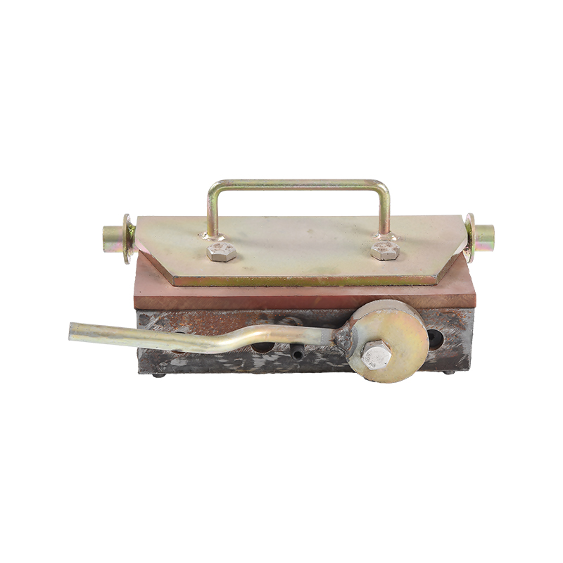
Precast Concrete Accessories That Work With Your Rebar Cage
In precast concrete manufacturing, the rebar cage is not just structural reinforcement — it's the platform to which dozens of Precast Concrete Accessories are attached before casting. These accessories include lifting inserts, form ties, anchor plates, electrical conduit supports, blockouts, sleeves, and embedded connection hardware. How you tie your rebar cage directly affects how accurately these accessories are positioned.
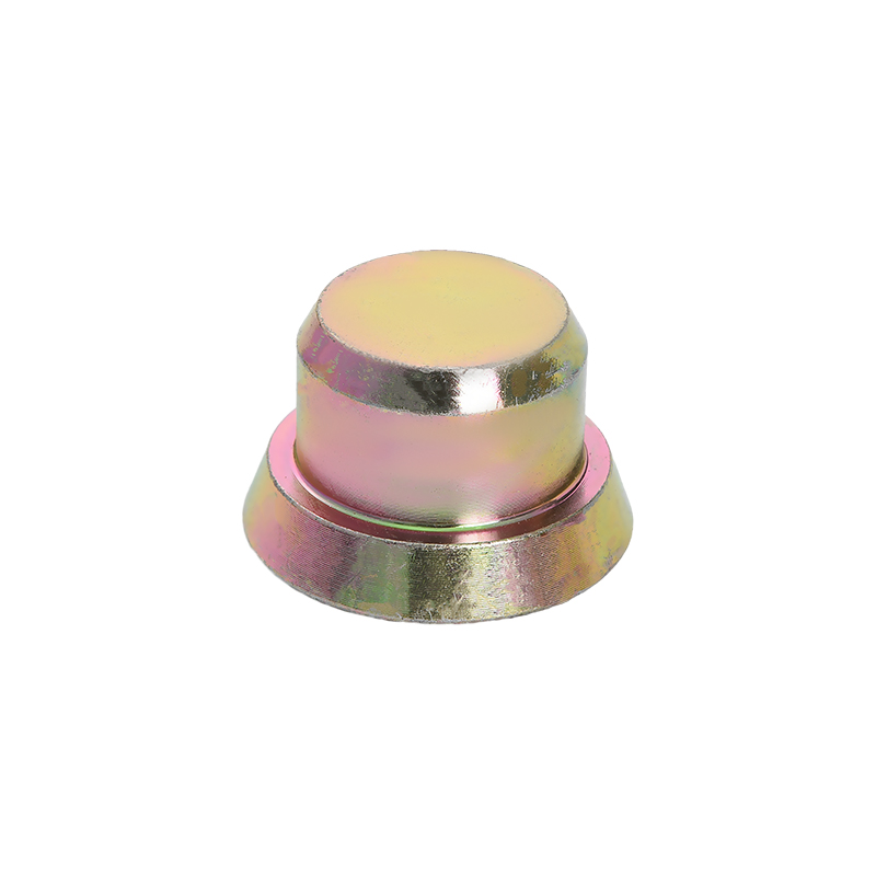
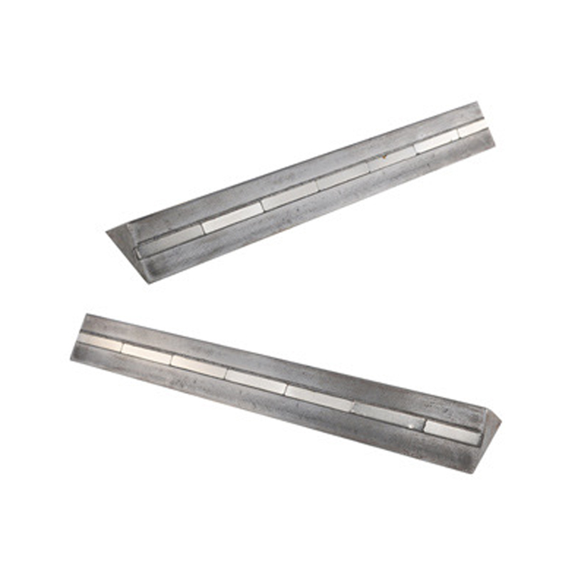
Bar Chairs and Rebar Spacers
Bar chairs and spacers are among the most commonly used Precast Concrete Accessories. They hold the rebar cage at the correct height above the form (bottom cover) and away from vertical form faces (side cover). The minimum concrete cover requirements under ACI 318 for precast members not exposed to weather is typically 3/4 inch for slabs and walls and 1.5 inches for beams and columns, but many precasters specify greater cover for durability.
- Plastic bar chairs: lightweight, resist corrosion, available in heights from 3/4 inch to 4 inches; standard choice for most precast applications
- Concrete block chairs: used where the point-load strength of plastic would cause the chair to punch into a soft form surface; often used in ground-bearing slabs
- Continuous wire spacers: used along the length of a bar to maintain side cover in wall panels; faster to install than individual chairs
- Circular spacers (donuts): clip directly onto the bar to maintain cover from formed vertical surfaces; available in standard cover increments of 3/4, 1, 1.5, 2, and 3 inches
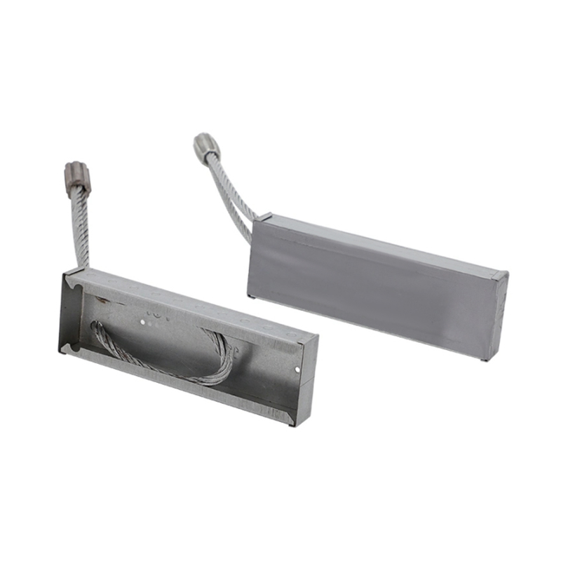
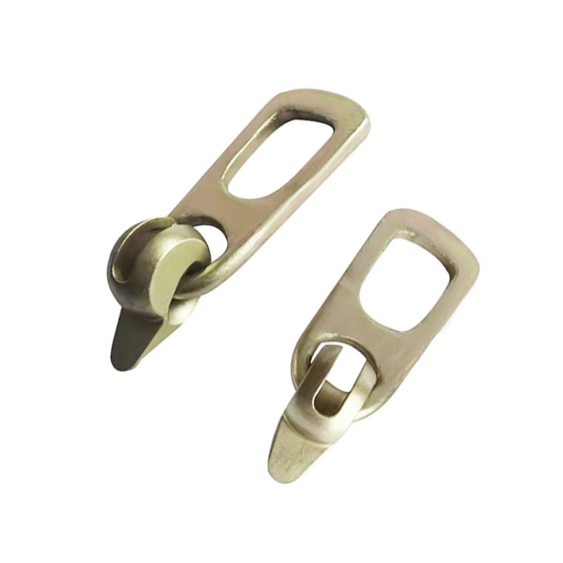
Lifting Inserts and Anchors
Lifting inserts are one of the most safety-critical categories of Precast Concrete Accessories. They must be positioned precisely within the rebar cage and tied securely to adjacent bars to prevent rotation or displacement during casting. A lifting insert that shifts even one inch from its specified location may fall outside its required embedment zone, potentially reducing its rated load capacity by 20–40% depending on edge distance effects.
Typical tie requirements for lifting inserts: the insert's anchor legs are tied to adjacent rebar using figure-eight or wrap-and-saddle ties — not snap ties. Insert manufacturers typically provide installation guides specifying minimum tie points, and these should be followed strictly.
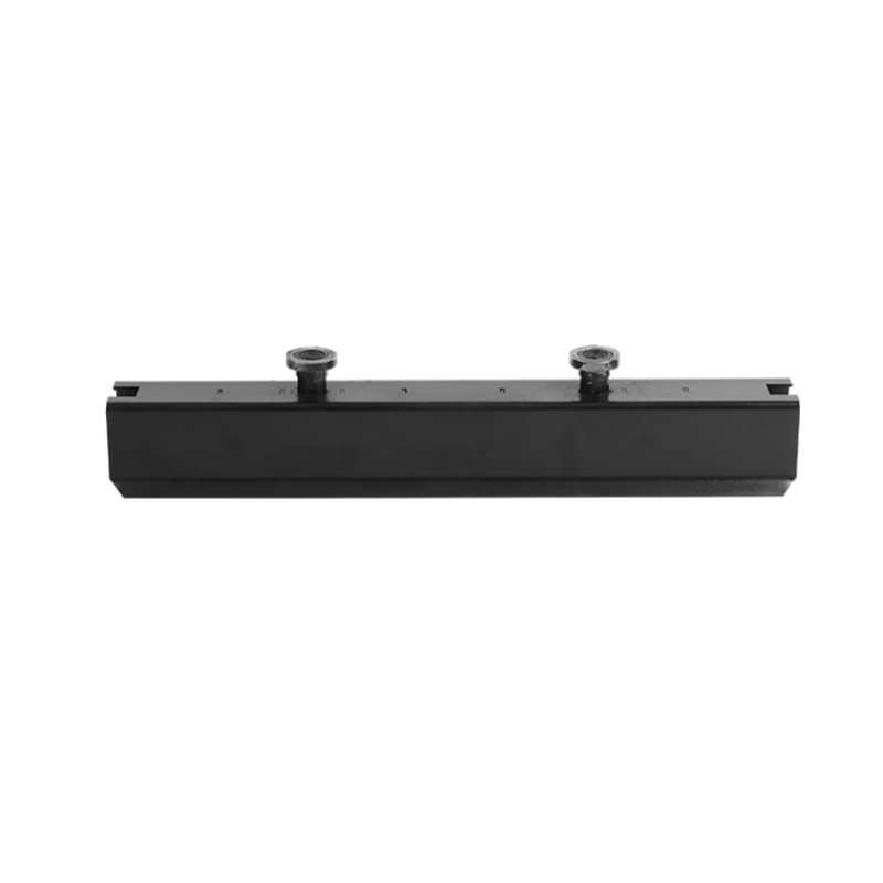
Embedded Plates and Connection Hardware
Steel plates, weld-on studs, and structural angles embedded in precast members require anchor bars tied directly to the plate anchors and into the rebar cage. The tie pattern must be rigid enough that the plate doesn't rotate during vibration. Plates larger than 6 inches square should be tied at a minimum of four points, with figure-eight ties at each corner stud.
Mechanical Rebar Couplers
Mechanical rebar couplers — used at construction joints to splice bars end-to-end — are a specialized category of Precast Concrete Accessories that interact directly with the tying process. When couplers are installed, the bars on each side of the joint must be tied to the cage independently before the coupler is threaded or swaged. Couplers certified to ASTM A1034 are required to develop 125% of the specified yield strength of the connected bar in tension — they are true structural elements, not just position holders.
Concrete Cover and Inspection: The Numbers That Matter
Concrete cover — the distance from the nearest bar surface to the outer concrete face — is the primary defense against reinforcement corrosion. Achieving specified cover depends entirely on correctly positioned bar chairs and a well-tied rebar cage that doesn't deflect under concrete placement forces.
| Member Type |
Exposure Condition |
Min. Cover (ACI 318) |
| Slab, wall, joist |
Not exposed to weather |
3/4 in (19 mm) |
| Beam, column |
Not exposed to weather |
1.5 in (38 mm) |
| Slab, wall, joist |
Exposed to weather (#5 and smaller) |
1.5 in (38 mm) |
| Slab, wall, joist |
Exposed to weather (#6 and larger) |
2 in (50 mm) |
| Beam, column |
Exposed to weather |
2 in (50 mm) |
| Footing (cast against earth) |
In contact with ground |
3 in (76 mm) |
Table 2: Minimum concrete cover requirements per ACI 318 for various member and exposure conditions
During inspection, the most common non-conformances found by quality inspectors are insufficient cover (bars resting on the form with no chairs) and missing ties that allow bars to spread apart. Industry data from precasters suggests that up to 15% of rejected panels involve cover-related issues that are directly traceable to inadequate chair spacing or improper cage tying.
A practical inspection checklist for tying reinforcing steel:
- Bar spacing matches drawings within tolerance (typically +/- 1 inch for slabs, +/- 3/8 inch for beams)
- Chairs or spacers are present at intervals specified on the placing drawings (typically every 4 feet for slabs)
- All lap splice lengths are correct and fully tied across the overlap zone
- Tie wire tails are bent inward, not protruding toward the surface
- All embedded accessories (inserts, plates, sleeves) are tied to the cage at minimum specified tie points
- No loose ties — every tied intersection holds under a hand push test
Tying Reinforcing Steel in Precast Production: Process and Quality Control
Precast concrete production differs from cast-in-place construction in several important ways that affect how tying reinforcing steel is managed. In a precast plant, cages are fabricated on dedicated jig tables or horizontal beds, then lifted into forms for casting. The cage fabrication process is highly systematized, and most plants use standard operating procedures (SOPs) that specify tie patterns, wire gauge, and accessory placement in detail.
Jig-Based Cage Fabrication
Steel jig tables with adjustable pin stops allow workers to position and tie rebar cages to precise dimensions before lifting them into forms. The jig ensures bar spacing and overall cage dimensions are correct before any wire is applied. In a well-run precast plant, cage fabrication on a jig can reduce dimensional rejects by 60–70% compared to tying in the form itself.
After the cage is tied on the jig, accessories are attached: bar chairs are clipped to the bottom bars, lifting inserts are wired to the specified locations, and any embedded hardware is secured. The completed cage is then lifted as a unit and set into the form, where edge spacers and additional accessories may be added before casting.
Documentation and Traceability
Quality precast manufacturers maintain documentation that traces each cage assembly back to the placing drawings, bar list, and the workers who fabricated it. This is not just good practice — it's required by standards such as PCI MNL-116 (Manual for Quality Control for Plants and Production of Structural Precast Concrete Products) and by many project specifications for bridge and building components.
When a non-conformance is found — say, a missing tie at a lifting insert or an out-of-position anchor plate — documentation traceability allows the fabricator to investigate the root cause and correct the process going forward. Without it, the same error recurs.
Tie Frequency in High-Production Precast
Not every intersection in a mat cage needs to be tied. Most specifications and the CRSI (Concrete Reinforcing Steel Institute) Placing Reinforcing Bars manual allow alternate-intersection tying in flat grid cages, provided tied intersections are not more than 18 inches apart in any direction. In practice, tying all perimeter intersections and every other interior intersection produces a cage that holds its geometry without the labor cost of tying every single crossing.
Where this rule changes: all intersections within 24 inches of a construction joint, all intersections within the embedment zone of a lifting insert or anchor plate, and all intersections at lap splices must be fully tied without skipping.
Common Mistakes When Tying Reinforcing Steel and How to Avoid Them
Years of field observation and quality audit data from precast and cast-in-place construction consistently reveal the same cluster of errors. Recognizing them is the first step to eliminating them.
Under-Tying Large Cages
On large cages — say, a 40-foot bridge girder cage with hundreds of intersections — workers sometimes skip ties to save time. The result is a cage that appears stable on the jig but spreads when lifted by crane or shifts during concrete vibration. Any bar movement during concrete placement is permanent; the concrete locks the bar wherever it settles when it stiffens. The fix is a tying frequency standard enforced by a foreman or QC inspector, not left to individual discretion.
Protruding Wire Tails
A twist tail left pointing outward toward a form face can migrate to within 1/4 inch of the concrete surface during vibration. Once the concrete sets, the tail rusts and stains the surface within the first few freeze-thaw cycles. In architectural precast, this is a finish defect. In structural precast, it indicates poor quality control. Every wire tail must be bent inward — it takes one extra second and eliminates the problem entirely.
Wrong Chair Heights
Using the wrong bar chair height is remarkably common on sites where multiple precast elements with different cover requirements are fabricated in the same area. Storing chairs by height in clearly labeled bins and verifying chair height against the placing drawing before fabrication starts is the simplest preventive measure. A misread of 3/4-inch chairs versus 1.5-inch chairs is not obvious visually during a quick walk-through; it only shows up in a physical measurement.
Inadequate Ties at Accessory Locations
As noted earlier, lifting inserts and embedded plates must be tied with figure-eight or wrap-and-saddle ties, not snap ties. A snap tie at a lifting insert anchor leg can rotate under the forces of concrete placement. When the concrete hardens, the insert may be angled rather than vertical, reducing its effective load capacity and potentially causing the threaded connection for the lifting hardware to bind or cross-thread.
Ignoring Bar Coating Compatibility
Epoxy-coated rebar requires compatible tie wire to prevent galvanic corrosion at the contact point. Black annealed wire tied to epoxy-coated bar creates a small galvanic cell at each nick or contact point in the coating. Use epoxy-coated or galvanized tie wire with epoxy-coated rebar, as specified in ASTM A775 and related standards. This detail is often overlooked in the field but is explicitly required in bridge and marine structure specifications.
Selecting Precast Concrete Accessories for Long-Term Performance
The selection of Precast Concrete Accessories — from bar chairs to lifting systems — has a direct impact on how long a precast structure performs without maintenance. Accessories that corrode, deform under load, or fail dimensionally after years in service can compromise the structural integrity of otherwise well-built members.
Material Selection for Bar Chairs and Spacers
Plastic (polypropylene or high-density polyethylene) bar chairs are the standard for most precast and cast-in-place work. They are chemically inert, do not corrode, and are dimensionally stable at the temperatures encountered in concrete curing. The relevant concern with plastic chairs is point-load performance under heavy rebar: #11 bars and larger, or bundled bar groups, can crack thin-walled plastic chairs if chair spacing is too wide. Use heavy-duty chairs rated for the expected load, or switch to steel wire chairs for large bar applications.
Steel wire bar chairs are appropriate for heavy cages and can span wider without deflecting, but they must be either epoxy-coated or positioned with a minimum cover of 1.5 inches above the form — bare steel chairs on a form face will telegraph a rust spot to the concrete surface within a few years.
Lifting Insert Load Ratings and Safety Factors
Lifting inserts must be selected based on the weight of the precast member, the number of pick points, the angle of the lifting slings, and the dynamic load factor applied during pick and swing operations. Most lifting insert manufacturers require a minimum safety factor of 4:1 under static load conditions, with dynamic factors of 2–3 applied to account for crane shock loads.
The interaction between lifting inserts and the rebar cage is critical. An insert that is not properly tied to adjacent bars does not develop its full embedment strength — the concrete cone breakout capacity depends on the insert being held in its design position with sufficient edge distance and embedment depth. Always review manufacturer installation instructions for minimum distances to edges and other inserts, and verify these against the placing drawings before fabrication begins.
Embedded Connection Hardware
Weld plates, stud rails, and structural angles embedded in precast members serve as connection points for field-erected structural steel, cladding systems, or adjacent precast members. Their positional accuracy requirements are tight — field erection tolerances for structural steel connections are typically +/- 1/4 inch in plan and elevation, which means the embedded plate must land within that tolerance after all fabrication and erection tolerances are stacked. Properly tying the anchor studs or anchor legs of embedded plates to the rebar cage, and placing the cage carefully on calibrated chairs, is how that tolerance is maintained.
Summary: Best Practices for Tying Reinforcing Steel in Precast and Cast-in-Place Work
The fundamentals of tying reinforcing steel are not complicated, but they require consistent attention at every step of cage fabrication and placement. Here are the key takeaways:
- Use 16 to 16.5 AWG annealed black wire for standard work; match wire type to rebar coating (galvanized or epoxy wire with coated bars)
- Apply saddle or figure-eight ties at high-movement locations — column cage hoops, construction joints, lap splices, and embedded accessory anchor points
- Bend all wire tails inward after twisting to prevent migration toward the concrete surface
- Use the correct bar chair height for the specified cover — verify against the placing drawing before fabrication, not after
- Tie all Precast Concrete Accessories (inserts, plates, sleeves) at the manufacturer-specified minimum tie points using figure-eight or wrap-and-saddle ties
- Consider battery-powered automatic tying tools for high-volume work — the productivity and consistency gains are significant
- Inspect cages before placement using a written checklist — cover, spacing, splice lengths, accessory positions, and tie tails
- In precast production, fabricate on jig tables and maintain documentation that supports traceability and quality audit requirements
A well-tied cage is invisible in the finished structure — which is exactly as it should be. The goal is concrete that performs precisely as designed, with reinforcement that stays exactly where it was placed, for the full design life of the structure.
 English
 Español
 русский
 日本語
日本語
 عربى
عربى