English
 Español
 русский
 日本語
日本語
 عربى
عربى

Content
- 1 What a Concrete Lifting Lug Actually Does
- 2 How a Lifting Lug Pairs with a Lifting Clutch
- 3 Load Ratings, Safety Factors, and the Role of Concrete Strength
- 4 Edge Distance, Anchor Spacing, and Embedment Depth
- 5 Installation Steps That Determine Whether a Lug Can Do Its Job
- 6 Common Lifting Lug Failures and How to Prevent Them
- 7 How to Select the Right Concrete Lifting Lug
- 8 Frequently Asked Questions About Concrete Lifting Lugs
- 8.1 1. What is the difference between a concrete lifting lug and an erection anchor?
- 8.2 2. Can a concrete lifting lug be reused after casting?
- 8.3 3. What safety factor is normally used for lifting lugs?
- 8.4 4. What is the minimum concrete strength required before lifting?
- 8.5 5. How deep should a lifting anchor be embedded in concrete?
- 8.6 6. What are insert magnets and why do they matter for lifting lug installation?
Concrete lifting lugs, also called lifting anchors or erection anchors, are the embedded steel connection points that transfer the weight of a precast concrete element from the crane hook to the concrete itself. Before a wall panel, beam, column, or staircase can be demolded, stacked, transported, or erected, at least one correctly sized lug must already be cast into the element. The most important lifting decisions - anchor type, working load limit, concrete strength at first lift, edge distance, and sling angle - have to be made at the design and formwork stage rather than on site.
This guide explains what concrete lifting lugs are, how they work with lifting clutches, how load ratings and safety factors behave in practice, and how to select and install the right anchor so every lift is predictable, repeatable, and safe.
What a Concrete Lifting Lug Actually Does
When a precast element leaves the mold, the lifting lug is the only load-bearing connection between the crane and several tons of concrete. A lug has two zones. The embedded zone is shaped with ribs, a bent plate, or a headed stud so it can develop a strong mechanical bond with the surrounding concrete. The exposed zone, usually a loop, an eye, or a flat socket, sits at the formwork face, and it is the part the lifting clutch grips during the lift.
How the Load Travels Through the System
The force path of a standard lift is: crane hook, sling or spreader beam, lifting clutch, exposed anchor head, embedded anchor body, and finally the concrete and its reinforcement. The anchor is the only link in this chain that cannot be inspected internally once the concrete has hardened. If the lug is undersized, or installed at the wrong angle, the problem stays hidden until the element is hanging from the crane. That makes the selection and installation stages more important than any other rigging component.
Common Lifting Lug Formats
Precast plants work with a small number of lug formats, and each one has clear advantages depending on the element geometry and the lifting method.
| Lug Format | Head Geometry | Connection Method | Typical Element Applications |
|---|---|---|---|
| Erection anchor | Single loop or eye on a headed stud | Spring-loaded lifting clutch | Wall panels, columns, beams, stair flights lifted at one or two points |
| Two-hole anchor | Flat plate with two drilled holes | Shackle pin or two-legged sling through both holes | Wide heavy slabs, double tees, transport saddles, multi-point lifting |
| Threaded socket anchor | Internally threaded sleeve flush with the surface | Detachable eyebolt or lifting spigot | Demolding threads, temporary bracing, repeated connection points |
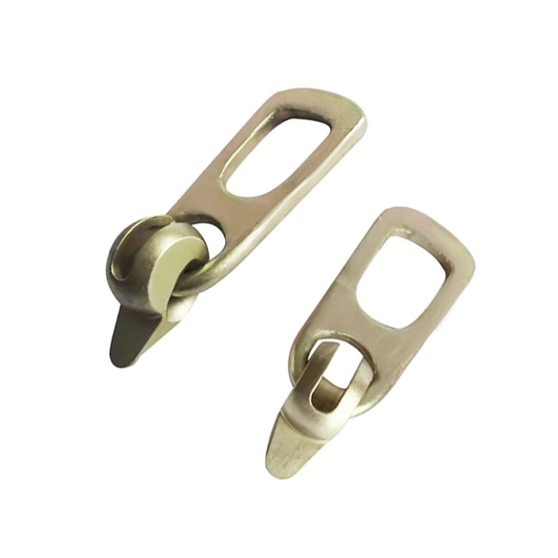
Erection anchors and two-hole anchors are the two formats commonly supplied for structural concrete lifting; both are designed to be used with a compatible clutch and sling hardware.
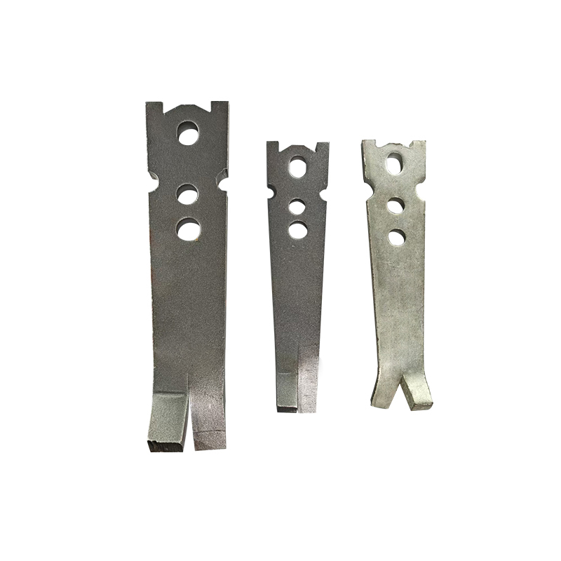 Erection Anchor for Structural Concrete LiftingThis erection anchor is designed to couple with a lifting clutch for securing precast concrete elements, featuring high load capacity, durable construction, and corrosion resistance for demanding environments.View Product →
How a Lifting Lug Pairs with a Lifting Clutch
A lifting clutch is the coupling component that locks onto the exposed lug head. The operator pulls back a spring-loaded pin, slides the clutch jaw over the anchor head, and releases the pin. The pin snaps into a machined locking groove in the anchor head, creating a positive mechanical connection that can be engaged in seconds, even when the element is out of reach. The same action works in reverse for releasing the clutch after the element is set.
Why use a clutch instead of a shackle and sling around a looped lug? The clutch connection is faster, tighter, and allows the anchor head to sit almost flush with the concrete surface, which simplifies demolding, stacking, and finishing. The flush head also avoids the protruding loops that can snag slings or cause injuries when workers walk between stacked panels.
Matching the Clutch to the Anchor Head
Clutch-to-anchor compatibility is a matter of geometry, not only brand. The clutch jaw must match the outer diameter and profile of the anchor head, and the locking pin must seat correctly in the groove. A clutch from one system used on an anchor head from another can look like a perfect fit, but the bearing area may be too small or misaligned, causing the head to deform under load. Always verify the manufacturer's compatibility table or use a complete anchor-and-clutch system.
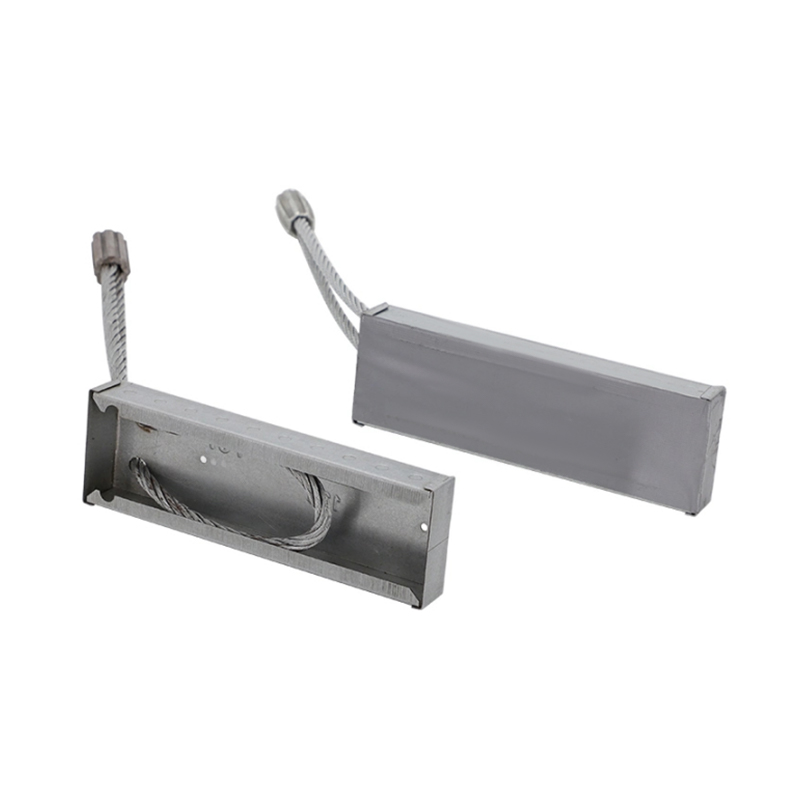
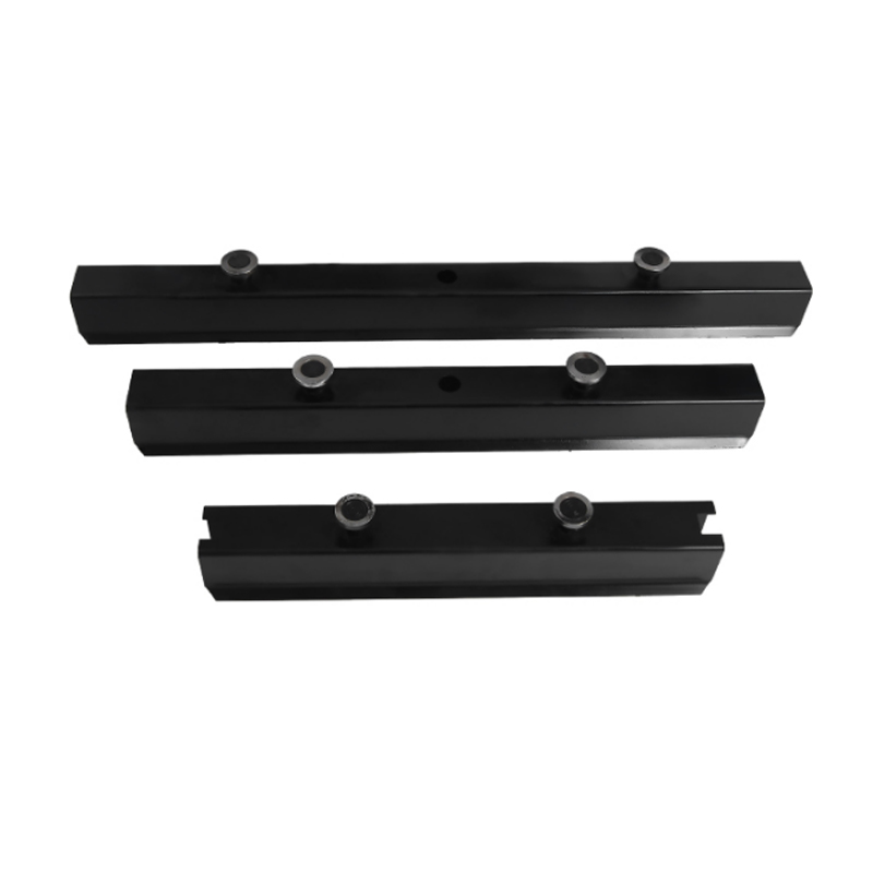 Magnetic Edge Touch System for Precast MoldsThis magnetic edge touch system combines built-in magnets and a welded shell for precast mold fixing, reducing manual repetition and supporting automated production with a robot hand-grasping hole design.View Product →
Load Ratings, Safety Factors, and the Role of Concrete Strength
The safe working load of a concrete lifting lug is not a single number printed on the anchor. It depends on four variables: the ultimate load of the anchor steel, the safety factor, the strength of the concrete at the moment of lifting, and the direction of the applied force.
Ultimate Load versus Working Load
The ultimate load is the force at which the lug or the surrounding concrete fails in a controlled test. The working load limit (WLL) is the maximum load allowed in service, calculated by dividing the ultimate load by the safety factor. For cast-in lifting anchors, safety factors of 2.5 to 4.0 are typical in precast practice. Human-lift applications, such as panels lifted above personnel, normally sit at the high end of that range.
Why Concrete Strength Is the Real Limit
In practice, the anchor steel is rarely the first component to fail. Pullout and concrete edge breakage occur when the concrete does not have the strength assumed in the load table. A typical precast plant waits until cube or cylinder tests show a minimum strength of 15 to 25 MPa before demolding, and most anchor load tables assume at least 20 to 30 MPa for the full rated capacity. Lifting with weaker concrete reduces the effective margin of safety even if the anchor is brand new.
| Angle between Sling Leg and Horizontal | Load Factor per Sling Leg | Practical Capacity Guidance |
|---|---|---|
| 90 degrees (vertical) | 1.00 | Full rated WLL available |
| 75 degrees | 1.04 | Negligible derating |
| 60 degrees | 1.15 | Reduce capacity by about 10% |
| 45 degrees | 1.41 | Reduce capacity by about 25% |
| 30 degrees | 2.00 | Not recommended for lifting lugs |
These load factors come from the basic trigonometric relationship between sling angle and leg force (1 divided by the sine of the angle), which is standard in rigging calculations. Most supplier load tables include a reduced working load for inclined lifts exactly because of this effect.
What Happens When the Angle Is Ignored
If the lifting plan assumes a vertical lift but the actual slings sit at 30 degrees, the force in each sling leg doubles. The anchor, which seemed correctly sized, is suddenly carrying twice its design load. Many yard failures happen this way, not because the anchor was undersized, but because the real sling angle was never included in the calculation. Define the actual lifting geometry before selecting the lug.
Edge Distance, Anchor Spacing, and Embedment Depth
A lifting lug only develops its full capacity when there is enough concrete around it to prevent a cone-shaped breakout. Three geometric values matter for every installation:
- Minimum edge distance - the distance from the center of the anchor to the nearest free edge. If this value is too small, the concrete spalls off during the lift.
- Minimum anchor spacing - the center-to-center distance between adjacent lugs. Overlapping breakout cones reduce the total capacity of the group.
- Minimum embedment depth - the depth of the anchor body inside the concrete. This controls the amount of concrete available to resist pullout.
| Working Load Class | Minimum Edge Distance | Minimum Anchor Spacing | Minimum Embedment Depth | Minimum Concrete Thickness |
|---|---|---|---|---|
| 3 t (30 kN) | 100 mm | 200 mm | 120 mm | 160 mm |
| 5 t (50 kN) | 120 mm | 240 mm | 140 mm | 200 mm |
| 8 t (80 kN) | 150 mm | 300 mm | 170 mm | 240 mm |
The values in the table are guidance based on typical precast lifting practice; exact numbers depend on the anchor type, concrete strength, and the supplier's load data, and the supplier's published values always take priority.
Installation Steps That Determine Whether a Lug Can Do Its Job
Even a correctly selected anchor will fail if it is not fixed firmly in the formwork before the concrete is placed. The steps below reflect the way anchors are positioned in modern precast plants.
- Fix the anchor to the formwork before placing concrete. Use a dedicated anchor positioner or magnetic holder so the lug head sits flush and cannot shift during vibration.
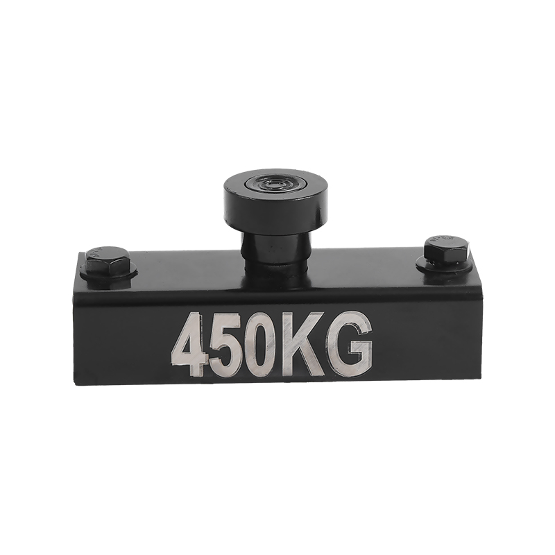
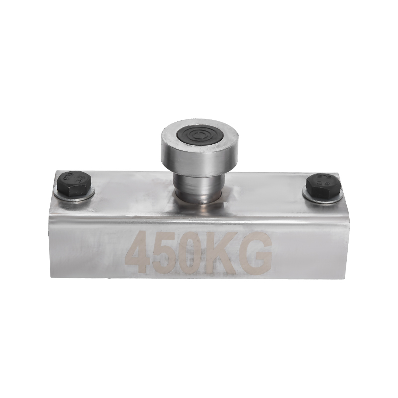
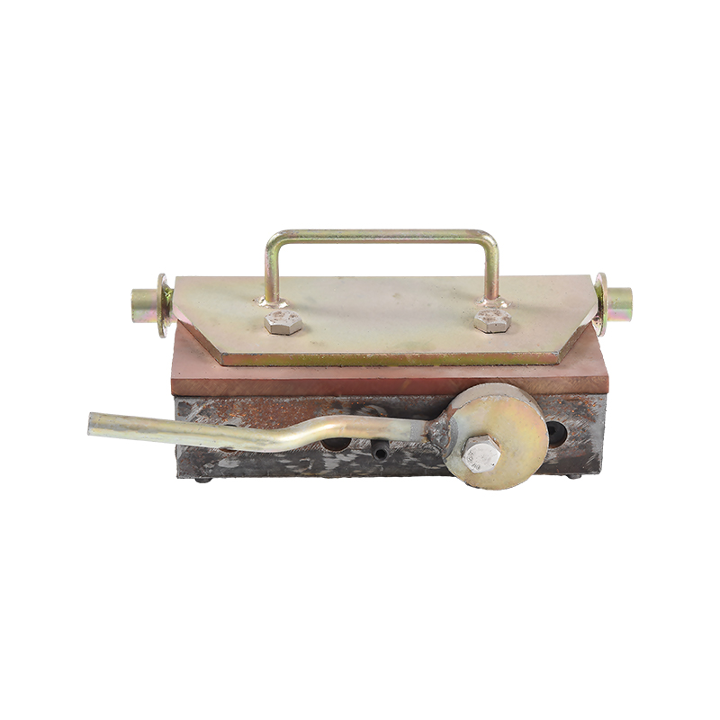
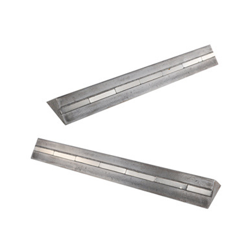
- On steel molds, magnetic positioners are the fastest option because they hold the anchor firmly and release instantly. Learn how insert magnets lock the anchor positioner to the form face before the concrete is poured.
- Seal the gap between the anchor head and the form face. If paste leaks into the locking groove or the threads, the clutch will not engage properly after demolding.
- Position the reinforcement so it does not collide with the anchor body. Standard practice is to keep at least 20 to 30 mm of clearance around the anchor so concrete can flow freely and compact around it.
- Compact the concrete in layers around the anchor area. Vibration should be sufficient to fill the space below the anchor head but not so aggressive that the anchor drifts from its position.
- Clean the anchor head immediately after demolding. Use a brush to remove paste from the locking groove, and inspect the head for deformation or damage.
- Record the measured concrete strength at the time of the first lift. This number tells you whether the anchor can be used at its full rated capacity.
Common Lifting Lug Failures and How to Prevent Them
Most lifting accidents with cast-in anchors follow a small number of predictable patterns. The table below lists the failures seen most often in precast yards and the controls that stop them.
| Failure Mode | Typical Cause | Prevention Measure |
|---|---|---|
| Anchor pulls out of concrete | Concrete below minimum strength at the time of the lift | Confirm cube or cylinder strength before lifting |
| Steel anchor bends or fractures | Force above the working load limit, usually from a shallow sling angle | Verify sling angles and respect the WLL |
| Concrete edge breaks off | Edge distance smaller than the minimum required | Follow the edge distance values in the load table |
| Clutch disengages during the lift | Clutch jaw or lock pin does not match the anchor head geometry | Use the clutch from the same anchor system, never a mixed setup |
| Anchor head hidden under hardened paste | Formwork not sealed around the anchor head | Seal the anchor-to-form interface before pouring |
Every one of these failures is preventable with a short pre-lift checklist. The time spent checking concrete strength, anchor geometry, and sling angles is far cheaper than a dropped panel.
How to Select the Right Concrete Lifting Lug
Selecting a lifting lug follows a five-step logic. Work through the element weight, the lift point arrangement, the sling geometry, the concrete thickness, and the formwork type, and the correct lug family appears by itself.
Step 1 - Calculate the Load per Lifting Point
Divide the total element weight by the number of lifting points, then apply the safety factor and the angle multiplier. Add the weight of any lifted accessories, such as spreader beams or formwork, to the element weight. The result is the minimum working load limit per lug.
Step 2 - Choose the Lug Family
For elements lifted at a single point with a clutch, an erection anchor is the usual choice. For wide or heavy elements lifted at two or more points with slings, a two-hole anchor distributes the force over a larger area and allows a shackle or sling leg to pass through.
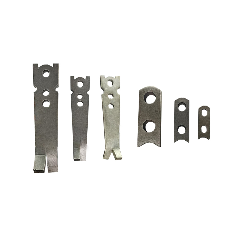 Two Hole Anchor for Multi-Point Precast LiftingThis two-hole anchor offers dual load-bearing holes for stable and balanced lifting of precast concrete elements, distributing force across a wider area when used with slings.View Product →
Step 3 - Verify the Concrete Thickness
The element must be thick enough for the required embedment depth. A 5 t lug with a 140 mm embedment needs a concrete thickness of at least 200 mm. If the element is thinner, you need a smaller lug, more lift points, or a specially designed anchor.
Step 4 - Match the Fixing Method to the Formwork
On steel forms, magnetic positioners reduce the positioning time to seconds and hold the anchor exactly at the right height. On timber or plastic forms, screw-on or nail-on plastic positioners keep the anchor in place but take slightly longer to mount.
Step 5 - Consider the Environment
Standard carbon steel lugs are suitable for indoor production and normal exposure. For elements that will be stored outdoors in coastal or corrosive environments, consider galvanized or stainless steel anchors so the exposed head does not rust and interfere with the clutch.
Compare the complete range of cast-in anchors, clutches, and formwork magnets before locking the design. A lug that is correctly sized, correctly embedded, and correctly matched to its clutch will survive hundreds of lifting cycles, while a mismatched set can fail on the first panel.
Frequently Asked Questions About Concrete Lifting Lugs
1. What is the difference between a concrete lifting lug and an erection anchor?
There is no practical difference. Lifting lug is the generic term for any cast-in lifting point. Erection anchor is the name used in precast product catalogs for the same component, usually when the anchor is paired with a matching clutch for panel erection.
2. Can a concrete lifting lug be reused after casting?
No. The lug is cast into the element and stays there for its entire service life. Only the clutch, sling, and shackle components are reused. If you need a removable connection point, use a threaded socket anchor with a detachable eyebolt.
3. What safety factor is normally used for lifting lugs?
Cast-in lifting anchors typically use a safety factor of 2.5 to 4.0 relative to the ultimate load. The exact factor depends on the anchor type, the lifting application, and the risk of personnel being under the load, which is why the supplier's documentation should always be followed.
4. What is the minimum concrete strength required before lifting?
Many precast plants wait for a cube strength of at least 15 to 25 MPa before demolding. However, most anchor load tables assume a minimum strength of 20 to 30 MPa for the full rated capacity. Check the table for the specific anchor, and if the measured strength is lower, reduce the lifting load proportionally or wait.
5. How deep should a lifting anchor be embedded in concrete?
For typical anchors in the 3 t to 8 t working load range, the embedment depth is usually between 120 mm and 170 mm. The exact value is printed in the anchor supplier's load table and depends on the anchor size and concrete strength.
6. What are insert magnets and why do they matter for lifting lug installation?
Insert magnets are magnetic positioning devices used on steel formwork. They hold the anchor positioner, chamfer, or other embedded part firmly against the form face, preventing the anchor from moving while the concrete is vibrated. They shorten the formwork setup time and improve the positional accuracy of every lifting lug.