English
 Español
 русский
 日本語
 عربى


Content
- 1 What Is a Shuttering Magnet and Why Does It Need to Be Switchable?
- 2 Anatomy of a Switchable Shuttering Magnet
- 3 The Physics Behind the Switch: How ON and OFF States Are Created
- 4 Step by Step: Activating and Releasing a Shuttering Magnet
- 5 Types of Switchable Activation Mechanisms
- 6 Holding Force Ratings and What They Actually Mean
- 7 Shuttering Magnets vs. Other Ways of Fixing Formwork
- 8 Factors That Affect Switching Performance and Holding Strength
- 9 Maintaining the Switchable Feature
- 10 How to Select the Right Shuttering Magnet for Your Precast Application
- 11 Frequently Asked Questions
- 11.1 How does the switchable feature of a shuttering magnet work?
- 11.2 Why does my shuttering magnet sometimes hold much less than its rated force?
- 11.3 Can a shuttering magnet be used with an 8 mm thick casting table?
- 11.4 How many magnets do I need for a given formwork size?
- 11.5 Should shuttering magnets be stored in the ON or OFF position?
- 11.6 Do shuttering magnets need electrical power to hold?
The switchable feature of a shuttering magnet works by rotating an internal permanent magnet core that redirects the magnetic flux path. In the ON state, the flux travels through the bottom plate into the steel casting table, creating a strong magnetic clamp. In the OFF state, the same flux is looped back inside the magnet housing, so the external magnetic pull drops almost to zero. Because the change is purely mechanical and requires no electrical power, the magnet holds formwork reliably through vibration and then releases instantly when the switch is turned back.
This article explains the mechanism in a practical way: what happens inside the housing, why the force appears and disappears, which switch designs exist, what force ratings really mean, and how to keep the switchable function accurate over years of service. The details apply to common precast concrete shuttering magnets with sintered NdFeB cores and to most switchable magnetic clamps used on steel casting tables.
What Is a Shuttering Magnet and Why Does It Need to Be Switchable?
A shuttering magnet, also called a magnetic box or formwork magnet, is a permanent-magnet assembly used to fix steel formwork against the ferromagnetic surface of a precast concrete casting table. Precast plants use these magnets to fasten side rails, edge profiles, chamfers, lifting-anchor sockets, and internal cores before pouring. After the concrete cures, the magnets are switched OFF and moved to the next mold.
The switchable design is not an extra convenience; it is the core reason the magnet can work in production. Without a switch, a strong permanent magnet would grab the steel table immediately, making alignment slow and removal dangerous. The switchable feature gives the crew three benefits that directly affect casting quality:
- Free positioning: you slide the formwork and the magnet while the magnet is OFF, then lock them together with one rotation of the switch.
- Quick release: switching OFF removes the attraction force, so the magnet lifts off without prying, hammering, or damage to the table or the magnet.
- Reusability: the same magnet can be cycled hundreds of times per production day, eliminating single-use consumables such as welded brackets or taped wedges.
In short, the switch converts an uncontrollable permanent magnet into a controllable clamp.
Anatomy of a Switchable Shuttering Magnet
To follow how the switch works, first recognize the parts inside a typical shuttering magnet. Although manufacturers differ in dimensions and housing shape, the functional components are the same.
| Component | Function | Typical Material |
|---|---|---|
| Outer housing | Encloses all parts, carries part of the magnetic flux, protects internal components against concrete slurry and impact | Painted mild steel or stainless steel |
| Magnetic core | Supplies the magnetic energy; sits on a rotating shaft | Sintered NdFeB, typically N35 to N45 grade |
| Rotating spindle / switch shaft | Connects the switch head to the magnetic core and transfers rotation from the top to the magnet | Hardened steel |
| Activation head | Key socket, lever, or handle that receives the operator’s movement | Steel, often with a rubber grip |
| Bottom contact plate | Interfaces directly with the casting table; transfers flux into the table; must be flat and clean | Machined mild steel |
| Adapter slots / T-slots | Allow attachment of formwork rails, side profiles, or custom brackets | Machined steel slots |
| Sealing plugs and bearing bushings | Keep water, cement slurry, and dust out of the rotating mechanism | Rubber or plastic plugs, bronze or POM bushings |
The housing is more than a protective shell. In a correctly designed magnet, the housing steel is part of the magnetic circuit. Its cross-section must be sufficient to carry the flux without saturating; otherwise, the force drops even when the switch is fully ON.
The Physics Behind the Switch: How ON and OFF States Are Created
A permanent magnet always generates magnetic flux; you cannot turn the flux off. What the switch changes is the path that the flux takes. Magnetic flux follows the route of lowest reluctance, which is the magnetic equivalent of electrical resistance. Ferromagnetic steel has very low reluctance; air and concrete have high reluctance. By rotating the internal magnet, the design deliberately changes whether the flux path goes through the magnet housing or through the steel casting table.
OFF state — internal short circuit. In the OFF position, the magnet core is oriented so that the flux jumps from one pole to the other inside the housing, crossing a small internal air gap. The flux completes its loop entirely inside the magnet body, so almost no field is present at the bottom face. The magnet can be placed on the table, moved, and aligned with little resistance.
ON state — external magnetic circuit. When the switch rotates the core by 90 or 180 degrees, the poles point toward the bottom plate. The flux now crosses the thin air gap between the bottom plate and the table, flows along the table, crosses back into the opposite pole, and returns through the housing. The table becomes part of the magnetic circuit, and the attraction between the magnet and the table is very strong.
Two-magnet opposing configuration. Many shuttering magnet designs use two separate magnet blocks mounted on the same shaft with opposite magnetization directions. Rotating the shaft moves the two blocks from a cancelling arrangement to an additive arrangement. In the OFF position the external fields cancel; in the ON position they add together. This gives a deeper ON/OFF ratio than a single rotating magnet block.
The role of the mild steel housing. Housing steel acts as a flux conductor that connects the top of the magnet to the bottom plate. It also shields the internal magnets from mechanical damage. Because the steel cross-section determines how much flux can pass, a housing with thin walls limits the maximum ON force even if the NdFeB core is large.
No permanent magnet ever reaches absolute zero external flux in the OFF state; some leakage remains. In practice, the residual attraction in OFF state is tuned to be low enough to slide the magnet by hand. Most sealed designs achieve an OFF pull of only a few kilograms, even for magnets with several tons of ON force.
Step by Step: Activating and Releasing a Shuttering Magnet
The switching procedure seems trivial, but small errors, such as placing a magnet on a rough table or turning the switch only halfway, reduce the holding force dramatically. Follow this sequence for reliable results.
Switch ON sequence
- Clean the contact surfaces: wipe the bottom magnetic face and the casting table in the mounting zone. Remove concrete chips, dried slurry, oil, and burrs. The air gap between the magnet face and the table must be as close to zero as possible.
- Align the formwork while the magnet is OFF: position the side rail or edge profile in its final line. Place the magnet next to the rail and slide it until the adapter slot engages the profile.
- Turn the switch to ON: use a key, lever, or handle to rotate the internal core toward the ON stop. Expect a clear increase in resistance as the flux closes, followed by a “snap” when the magnet seats flat against the table.
- Check flush contact: after activation, run a fingernail or a thin feeler gauge along the edges. If you find a lifted corner, the contact face has contamination or the table has a high spot.
- Confirm the working load: remember that the rated pull force applies under ideal conditions. If the formwork will experience heavy vibration or high concrete pressure, add extra magnets rather than relying only on the theoretical maximum.
Switch OFF / release sequence
- After the concrete has cured, clean slurry from the top of the magnet and around the lever or key socket so no foreign material falls into the mechanism.
- Rotate the switch back to OFF. The external pull force disappears almost immediately; if it does not, stop and check that the core has actually reached the OFF stop instead of being blocked by debris.
- Lift the magnet vertically first. Once the face is clear of the table, move it sideways to the storage area.
- Clean the face and store the magnet in the OFF position, with the bottom surface protected from dust and metal chips.
Types of Switchable Activation Mechanisms
Manufacturers build the same magnetic-core concept into different bodies depending on how fast and how convenient the operator wants the switching action to be.
Key-Operated Rotary Magnets
In the simplest version, a hexagonal or square key socket sits in the top of the housing. The operator inserts a tool and turns it 90 or 180 degrees. This design is inexpensive, compact, and easy to clean, but it creates an extra step because the crew must carry the key and insert it into every magnet. It remains a good choice for low-cycle applications and for magnets that stay in one position for several days.
Lever-Activated Shuttering Magnet Box Levers
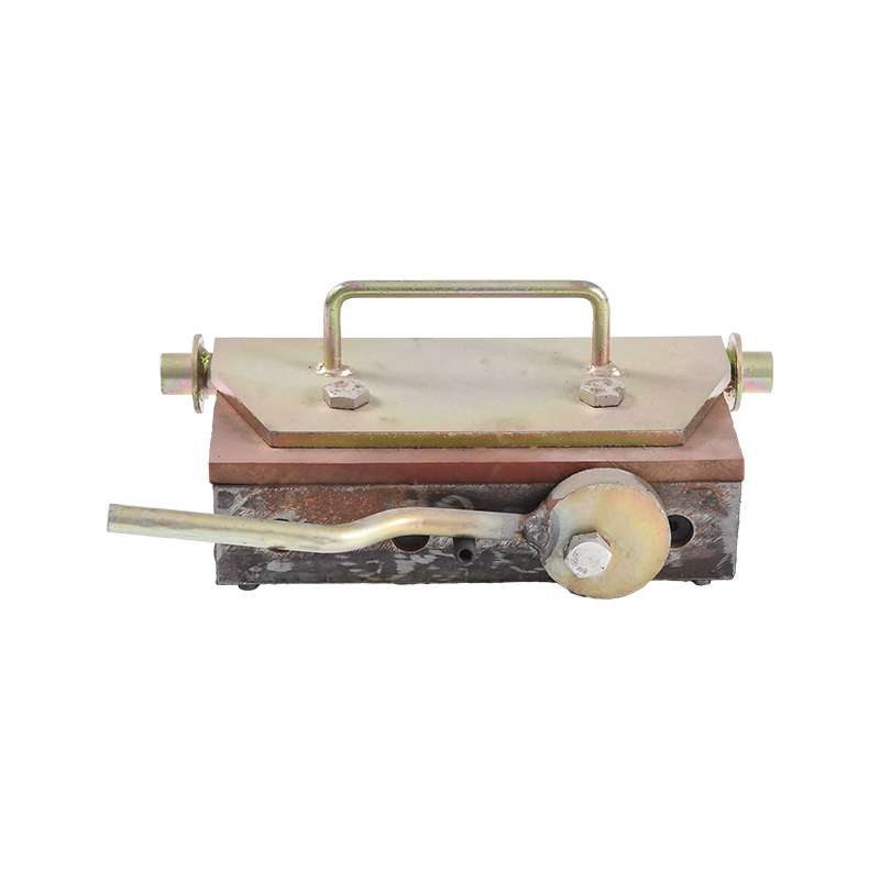
Lever-operated designs integrate a short steel lever into the housing. Pressing the lever rotates the core in one smooth stroke, so no separate tool is needed. The lever also gives the operator a direct feel for whether the magnet has reached the ON stop. On a production table with dozens of magnets, the time saved per magnet adds up quickly. You can read a deeper explanation of the lever operation principle in shuttering magnetic box levers in our technical article.
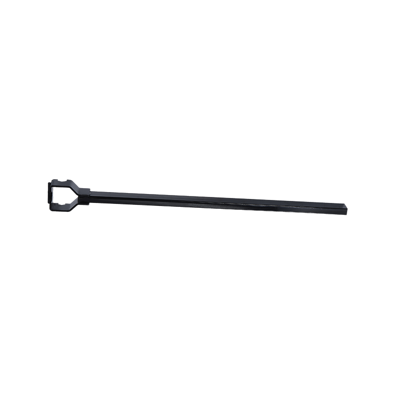 Lever-Operated Shuttering Magnet Box for Quick On/Off ControlThis magnet integrates a lever into its housing, letting operators toggle the magnetic core with one stroke. It suits production tables where many magnets are used, saving time and improving handling efficiency.View Product →
Shuttering Magnet with Handle
Combining the switch with a lifting handle is a practical solution for heavy magnets. The operator moves the magnet into place by the handle, then rotates the same handle to activate the core. This saves hand changes and is particularly useful when one worker must manage a 20-40 kg magnet alone.
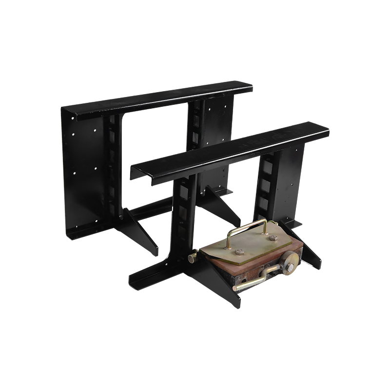 Shuttering Magnet with Integrated Lifting HandleThis design combines a lifting handle with the switch mechanism, allowing a single worker to position and activate heavy magnets without changing grips. Ideal for magnets weighing 20-40 kg.View Product →
Combination Box Magnets and Frame Systems
For long straight edges, manufacturers place several magnetic cores inside one rectangular steel frame, with a single row of switches along the top. These box magnets spread the holding force over a larger area, reduce magnetic pressure on the table surface, and prevent thin tables from being dented. They also allow very high total clamping force along a continuous formwork line.
Solenoid-Assisted Auto-Release Magnets
A less common variant adds a short electrical pulse to assist in the release step. The holding force is still supplied by permanent magnets, but the solenoid generates a brief opposing field that helps break the residual sticking during demolding. This design requires a power source near the table and more complex controls, so it is used mainly in automated or semi-automated precast lines.
Holding Force Ratings and What They Actually Mean
When a manufacturer states that a shuttering magnet has a 2,000 kg holding force, that number refers to a specific test condition: a clean, flat reference plate, usually 12 mm or thicker, a dry contact, and a pull direction perpendicular to the plate surface. Real conditions on a casting table are often less favorable.
| Force Class | Reference Table Thickness | Recommended Continuous Working Load | Typical Formwork Use |
|---|---|---|---|
| 500 kg | 8-10 mm | 200 kg | Small edge profiles, chamfers, light inserts |
| 1,000 kg | 10 mm | 400 kg | Standard side rails on thin pallets |
| 2,000 kg | 12 mm | 800 kg | Heavy side rails on standard tables |
| 3,000 kg | 12-14 mm | 1,200 kg | Large cores, high concrete pressure zones |
| 4,000 kg | 14-16 mm | 1,600 kg | Deep beams and heavily reinforced elements |
Producers usually apply a safety factor of 2.0 to 3.0 when converting rated pull force into a recommended working load. The safety factor covers three effects: the lateral (shear) component of concrete pressure, the dynamic loads of vibration, and the local loss of force caused by a slightly dirty or uneven contact face.
Here is a simplified calculation based on common precast engineering practice. Fresh concrete exerts lateral pressure of roughly 30 to 50 kN per square meter at the lower part of a 1.2 m high panel, depending on slump, setting rate, and vibration method. If one side of a mold measures 0.4 m wide by 1.2 m high, the area is about 0.48 square meters, giving 14.4 to 24 kN of side load. With a safety factor of 2.5, the required rated force becomes 36 to 60 kN, or about 3,700 to 6,100 kgf. In practice, you would spread several 2,000-3,000 kg class magnets along that line rather than rely on one large magnet.
The important number is not the highest pull force, but the force that the magnet can hold under the exact table and contamination conditions of your plant. Always ask the supplier for the reference test procedure and the measured ON/OFF force values.
Shuttering Magnets vs. Other Ways of Fixing Formwork
Switchable magnets are not the only fastening method in precast production. The following table compares the four common approaches in terms of what matters on the production floor.
| Method | Setup Speed | Need to Modify the Table? | Repositioning Effort | Typical Labor / Tools | Reuse Potential |
|---|---|---|---|---|---|
| Switchable shuttering magnet | Seconds per magnet; no tools | None | Rotate switch OFF and slide | One worker, no power | Very high; thousands of cycles |
| Mechanical clamps / threaded inserts | A few minutes per point | Requires drilled holes or tapped inserts | Unscrew, reposition, retighten | Spanner / wrench; corrosion risk | High, but threads wear |
| Welded tabs / brackets | 10-20 minutes per point including welding and grinding | Leaves weld spots, grinding marks, heat distortion | Cut off and re-weld | Welder + grinder | Low; destructive removal |
| Vacuum clamps | Depends on vacuum pump setup | None, but table must be airtight | Release vacuum, slide | Pump, hoses, valves | Medium; sensitive to contamination |
Magnets win on changeover speed and table preservation, but they require a ferromagnetic table. For non-magnetic formwork materials such as aluminum or plastic, or for extremely high lateral loads such as those in heavily reinforced load-bearing walls, a mechanical backup is sometimes necessary.
Factors That Affect Switching Performance and Holding Strength
Contact Flatness and Surface Contamination
The contact between the bottom face and the table is the most sensitive element of the whole magnetic circuit. Even a thin layer of dried cement changes the air gap from near-zero to several tenths of a millimeter. Because magnetic force falls sharply with air gap, the effective holding force can drop by 30-50% with visible residue.
Casting Table Thickness and Steel Grade
The flux has to travel through the table top plate, and a thin plate limits the flux that can pass. Most rated values assume a 12 mm reference plate. On an 8 mm plate, the same magnet may deliver only 60-70% of its rated pull.
| Table Steel Thickness (mm) | Approx. Relative Holding Force (%) |
|---|---|
| 6 mm | 55 |
| 8 mm | 70 |
| 10 mm | 85 |
| 12 mm | 100 |
| 16 mm | 100 |
For thin pallets, choose a larger number of smaller magnets instead of a few large ones. Large magnets concentrate flux and can locally saturate the table top plate, reducing the effective holding area.
Vibration and Shear Loads During Casting
Concrete vibrators generate strong side loads. A magnet holds best in the direction perpendicular to the contact surface. Sideways forces are resisted mainly by friction between the magnet face and the table. The ON state has no active hold besides this friction, so if the lateral force exceeds the friction limit, the magnet slides. Increasing the number of magnets, and therefore the total normal force, is the standard fix.
Temperature
Sintered NdFeB magnets lose a percentage of their flux when heated. Common N35-N45 shuttering magnet grades begin a noticeable reversible loss above about 80 °C and suffer irreversible structural damage above the maximum operating temperature, typically 80-100 °C for standard grades. In normal precast work, concrete temperatures stay in a safe range, but you should never clean a magnet with a steam jet or leave it on a heat-treated table.
Switch Torque and Mechanical Wear
A smooth, consistent switching action depends on the internal spindle and the stop pins. After a few thousand cycles, concrete slurry can enter through a worn seal and make the switch stiff or, worse, prevent the core from reaching the full ON position. A magnet that looks perfectly fine may lose force simply because the core stopped 10 degrees short of the correct alignment.
Maintaining the Switchable Feature
The switch is a wearing part, but with simple daily habits it stays reliable for years. The maintenance routine below reflects common precast plant practice.
- Clean after every shift: wipe the bottom face, adapter slots, and lever/key socket with a damp cloth. Do not let concrete harden on the face.
- Check the switching torque: if the lever becomes hard to operate, open the switch cover, flush out slurry, and re-grease the pivot with a lithium-based grease.
- Run a force check monthly: place the magnet on a reference plate in the ON state and try to lift it with a rated pull tester or a calibrated scale. If the force drops more than 15-20% below the mark, send the magnet for internal inspection.
- Inspect the bottom face flatness: use a straight edge. Rounded corners, scratches, or dishing on the face mean reduced contact and lower force.
- Store in the OFF state: this prevents the magnet from collecting steel chips and prevents accidental pinching in the storage rack.
- Protect the lever, key slot, and plugs: replace cracked rubber plugs immediately; they are the only barrier between the rotating core and concrete slurry.
How to Select the Right Shuttering Magnet for Your Precast Application
Choose a magnet the way a structural engineer chooses a fastener: calculate the load, apply a safety margin, and then check the actual working surface. A simple selection workflow helps.
- Calculate the lateral concrete pressure for the tallest pour on the element, typically 30-50 kN per square meter for internal vibration curves.
- Multiply by the length of formwork each magnet will serve to find the side load per magnet position.
- Apply a safety factor of at least 2.5 to convert the required working load into a rated pull class.
- Measure the table thickness; do not specify magnets whose flux demand exceeds the table’s magnetic carrying capacity.
- Choose the activation style, key, lever, or handle, based on the crew’s production rhythm.
- Confirm the adapter slot matches the width and hook profile of your side rails.
For standard precast molds, a rectangular lever-operated magnetic box is a balanced choice: it activates without tools, releases quickly, and spreads the pull over a stable footprint. If the line already has key sockets and the crew is comfortable with them, the simpler key version saves money.
For general-purpose clamping on painted mild-steel tables, carbon steel magnetic boxes provide the most cost-effective structure, while stainless steel versions fit wet-casting environments where rust is a concern.
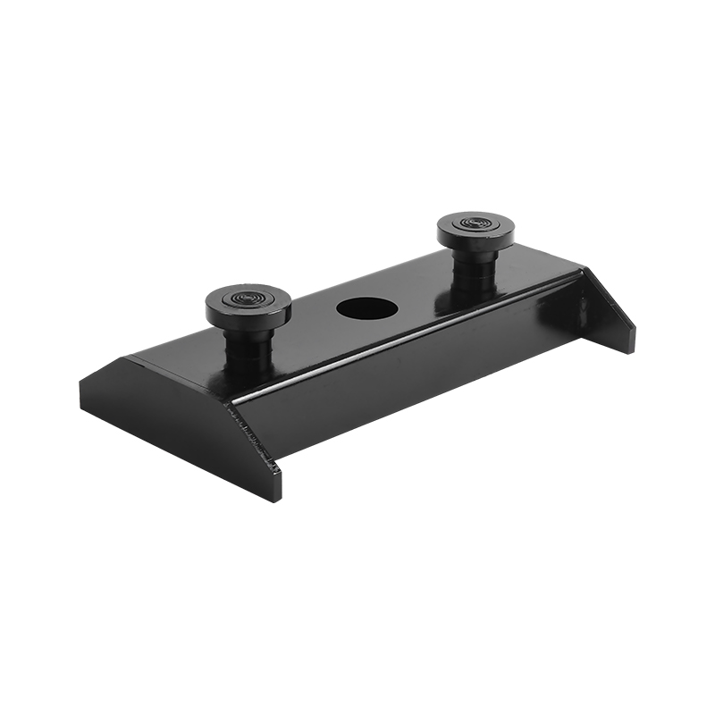 Carbon Steel Magnetic Box for General-Purpose ClampingThis cost-effective carbon steel magnetic box offers strong magnetic adhesion on painted mild-steel tables. It is suitable for general clamping tasks, while stainless steel alternatives are better for wet-casting environments.View Product →
Frequently Asked Questions
How does the switchable feature of a shuttering magnet work?
A rotating internal permanent magnet core redirects the magnetic flux. In the ON state, flux flows through the bottom face into the steel table, producing a strong clamping force. In the OFF state, the flux circulates internally within the magnet housing, reducing external pull so the magnet can be moved by hand.
Why does my shuttering magnet sometimes hold much less than its rated force?
The usual causes are a contaminated or uneven contact face, a thin casting table, an incomplete switch rotation, or internal mechanical wear. Start by cleaning the face and the table; then check the switch stroke; then test the magnet on a clean 12 mm reference plate.
Can a shuttering magnet be used with an 8 mm thick casting table?
It can, but the effective holding force will be lower than the rated value. On a table thinner than 10 mm, choose more small magnets rather than fewer large ones to avoid saturating the top plate and to distribute the magnetic pressure.
How many magnets do I need for a given formwork size?
Divide the total lateral concrete load by the safe working force per magnet, about 40-50% of the rated pull depending on your safety factor, then add 10-15% extra for vibration and uneven contact. For example, a 1.2 m high, 3 m long line requiring 40 kN of rated clamp force can be covered by four to six 2,000 kg class magnets.
Should shuttering magnets be stored in the ON or OFF position?
Store them OFF. This avoids attracting metal dust, prevents accidental pinching when stacking, and keeps the magnet face clean. It also prevents gradual magnetization of nearby tools and steel plates over time.
Do shuttering magnets need electrical power to hold?
No. With the exception of solenoid-assisted release versions, shuttering magnets use only permanent magnets. The holding force is continuous and free of energy cost; electricity appears only in special auto-release designs.