English
 Español
 русский
 日本語
 عربى

Content
- 1 Carbon Fiber Reinforcement in Concrete: A Direct Answer
- 2 What Carbon Fiber Reinforcement Actually Does Inside Concrete
- 3 Measured Performance Gains: Quantified Data You Can Use
- 4 Fiber Length and Dosage: What Works in Practice
- 5 Application Methods: Chopped Fiber, Fabric, and Grid Reinforcement
- 6 Carbon Fiber in Precast Concrete: Thinner Members, Tighter Tolerances
- 7 Cost, Sustainability, and Long-Term Performance
- 8 Frequently Asked Questions
- 8.1 Can carbon fiber replace rebar in structural concrete?
- 8.2 What is the typical carbon fiber dosage in concrete?
- 8.3 What are the main disadvantages of carbon fiber reinforced concrete?
- 8.4 Does carbon fiber improve freeze-thaw durability?
- 8.5 How does carbon fiber compare with steel fiber in concrete?
Carbon Fiber Reinforcement in Concrete: A Direct Answer
Yes, carbon fiber reinforcement works in concrete. When short chopped carbon fibers are added at a volume fraction of roughly 0.2% to 0.5% (about 3 to 8 kg per cubic meter), the material stops behaving like a brittle ceramic and starts behaving like a tough composite. The most direct way to see this is in laboratory flexural tests: plain concrete cracks and loses load capacity almost immediately after reaching about 3 to 4 MPa in tension, while a carbon-fiber-reinforced concrete beam continues to carry load, holding cracks tightly closed and showing a measurable increase in flexural strength of 15% to 30%.
The SHRP-92-605 report from the US Strategic Highway Research Program documented an even larger gain: concrete containing carbon fiber at 1.0% of cement weight showed up to 85% improvement in strength and a significant increase in freeze-thaw durability compared with plain concrete. That is not theoretical. It is measured data from a government research program, and it explains why carbon fiber has moved from aerospace and automotive parts into bridge overlays, precast panels, repair mortars, and thin architectural concrete shells.
However, a clear answer requires one important boundary: carbon fiber does not replace steel rebar in columns or heavily loaded beams. Steel carries the primary bending and shear forces in structural members. Carbon fiber reinforcement instead controls microcracking, increases fracture energy, improves impact resistance, and makes the concrete itself more durable. In many cases, the two systems work together: rebar handles structural demand while carbon fiber protects the cover concrete and extends the member's service life.
What Carbon Fiber Reinforcement Actually Does Inside Concrete
The mechanism is mechanical, not chemical. Carbon fibers are 5 to 10 microns in diameter, roughly one-tenth the diameter of a human hair. Because they are short, stiff, and strong, they disperse through the cement paste and form a three-dimensional network. When tensile stress opens a microcrack, fibers bridging that crack resist further opening and transfer load back into the paste. That single action changes how concrete fails: instead of one large crack propagating across the whole member, you get many small controlled cracks, each one held by fibers.
Four Definite Effects
- Crack control: plastic-shrinkage cracking in the first 24 hours after casting is reduced by more than 50% compared with plain concrete, per ACI 544.4R design guidance.
- Higher flexural strength: typical laboratory gains in the range of 15% to 30% when using 0.3% to 0.5% fibers by volume.
- Increased fracture energy: plain concrete absorbs roughly 100 to 200 J/m² in a standard panel test; carbon-fiber-reinforced concrete can reach 300 to 500 J/m².
- Freeze-thaw durability: the SHRP-92-605 report measured an 85% strength improvement with 1.0% carbon fiber by cement weight, along with better resistance to repeated freeze-thaw cycles.
| Property | Plain Concrete | Carbon-Fiber Concrete | Steel-Reinforced Concrete |
|---|---|---|---|
| Tensile strength | 3–4 MPa | Moderate gain; crack resistance improves most | 400–550 MPa design yield |
| Crack behavior | One wide crack at failure | Many tightly controlled microcracks | Crack width controlled by rebar and cover |
| Corrosion risk | No embedded metal, but cracks admit moisture | None; carbon fiber is corrosion-immune | High if cracked and exposed to chlorides |
| Density | ~2,350 kg/m³ | ~2,350 kg/m³ with minor reduction | ~2,500 kg/m³ with steel |
The practical takeaway is simple. Carbon fiber works where concrete experiences tension, shrinkage restraint, impact, or freezing and thawing. It does not replace the structural reinforcement cage, but it makes the surrounding concrete significantly harder to break apart.
Measured Performance Gains: Quantified Data You Can Use
For engineers making material selections, general claims are not enough. The numbers below come from published research and standard testing methods, and they give a realistic picture of what carbon fiber reinforcement delivers in the field.
- Freeze-thaw durability improvement up to 85% when carbon fiber is added at 1.0% of cement weight. Source: SHRP-92-605, Strategic Highway Research Program, US National Research Council.
- Flexural strength increase of 15% to 30% at 0.3% to 0.5% fiber volume fraction, confirmed by beam tests following ASTM C1609/C1609M.
- Fracture energy rise from 100–200 J/m² to 300–500 J/m² in round panel tests per ASTM C1550, indicating dramatically better post-crack toughness.
- More than 50% reduction in plastic-shrinkage cracking in the first 24 hours after casting, based on ACI 544.4R evaluation methods.
- Fiber count is high: adding 1 kg of carbon fiber gives roughly 100 million individual fibers. Even at low dosage, the crack-bridging network is dense.
Note that the 85% figure is tied to the specific SHRP mix design of 1.0% fiber by cement weight, which corresponds to roughly 4 kg/m³ in a typical 400 kg/m³ cement mix. Most commercial pours use 0.2% to 0.5% by volume, giving lower but still meaningful improvements while keeping the concrete workable.
Fiber Length and Dosage: What Works in Practice
Carbon fiber is not a single product. Short chopped strands, chopped fiber bundles, and milled fibers behave differently in fresh and hardened concrete. Three parameters matter most: fiber length, dosage, and aspect ratio.
Length Selection Guide
| Fiber Length | Typical Dosage | Best Applications |
|---|---|---|
| 6 mm | 0.2%–0.4% by volume | Self-consolidating concrete, repair mortar, thin overlays |
| 12–18 mm | 0.3%–0.5% by volume | Precast panels, bridge overlays, parking decks |
| 30 mm and longer | 0.4%–1.0% by volume | High-toughness slabs, industrial floors, blast-resistant walls |
Mixing and Workability Requirements
- Dry-blend first. Mix carbon fiber with aggregates and cement for 3–4 minutes before adding water. This avoids fiber clumping and creates a uniform dispersion.
- Expect slump loss. Carbon fibers increase surface area and internal friction. A mix that starts at 180 mm slump can drop to 140 mm after fiber addition; use superplasticizer to compensate.
- Use air-entraining admixtures carefully. High carbon fiber content can trap air; monitor air content during trial batches.
- Confirm dispersion before pumping. Some fiber products are pre-dispersed bundles; others need additional mixing time to fully open and separate.
The economic sweet spot for most structural applications is 0.2% to 0.5% fiber by volume. Beyond that range, performance gains continue but workability drops sharply and material cost rises quickly.
Application Methods: Chopped Fiber, Fabric, and Grid Reinforcement
Carbon fiber appears in three distinct forms in concrete construction. Choosing the right form depends on whether you are reinforcing the concrete itself or adding external strength to an existing member.
1. Chopped Carbon Fiber Mixed Into Concrete
This is the simplest method and the one relevant to most concrete producers. Chopped fibers are added to the mixer, distributed uniformly, and cast like conventional concrete. Best uses are bridge deck overlays, repair mortars, precast panels, and UHPC structural components. The fiber improves the concrete's own properties, not the member's overall structural capacity.
2. Externally Bonded Carbon Fiber Fabric or Laminate
Carbon fiber reinforced polymer (CFRP) sheets or laminates are bonded to the tension face of beams and slabs with epoxy. This is a well-established strengthening method for parking garages, bridges, and industrial floors where added reinforcement cannot be cast inside the member. A typical CFRP wrap with a 300 g/m² fiber areal weight can increase flexural capacity by 10% to 40% depending on the number of layers and anchorage details.
3. Carbon Fiber Grid and Textile Reinforcement
Open carbon fiber grids are placed in thin overlays or used as durable reinforcement in non-load-bearing walls. The grid keeps cracks tightly closed in the cover zone and resists corrosion where de-icing salts are present. This approach is especially popular for bridge deck overlays and prefabricated façade panels.
Typical Application Scenarios
- Bridge deck overlays: chopped carbon fiber resists reflective cracking and chloride penetration.
- Repair mortars: short carbon fiber provides dimensional stability and reduces shrinkage cracking in thin patches.
- UHPC components: carbon fibers complement the dense matrix and supply durability that steel fibers cannot match when chloride exposure is severe.
- Parking structures: textile carbon reinforcement keeps cracks below 0.2 mm, protecting embedded metal from salt-laden water.
Carbon Fiber in Precast Concrete: Thinner Members, Tighter Tolerances
Precast producers get an outsized benefit from carbon fiber because they control the casting environment. A plant can use carbon-fiber-reinforced mixes to produce thinner wall panels, lighter architectural elements, and U-shaped shells that would otherwise require dense steel reinforcement to prevent handling cracks. The reduction in self-weight directly reduces lifting cost and transportation cost.
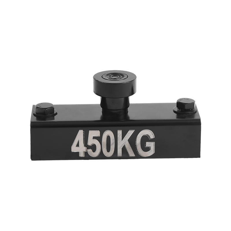
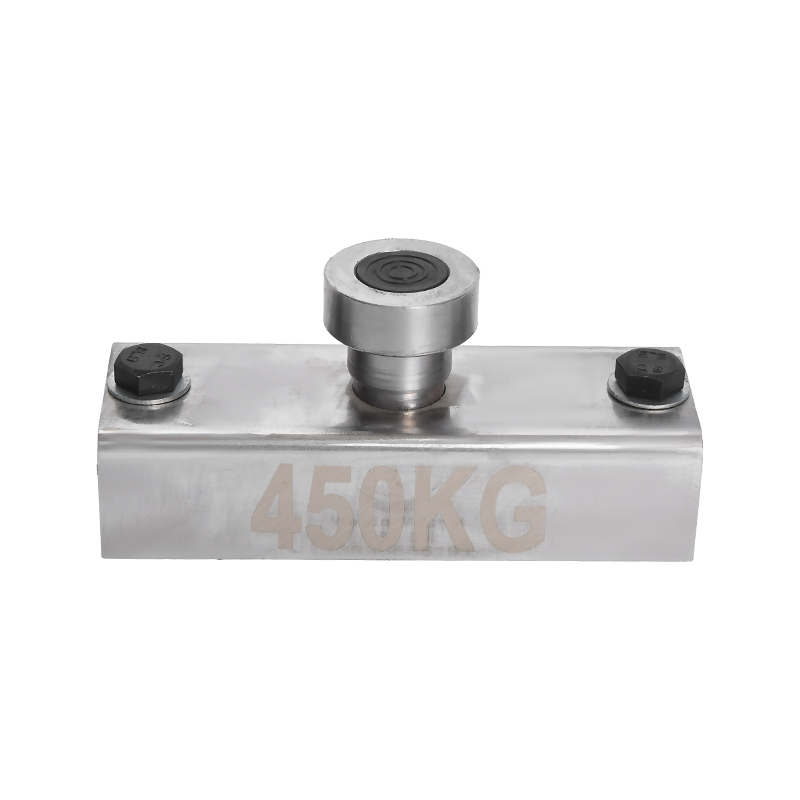
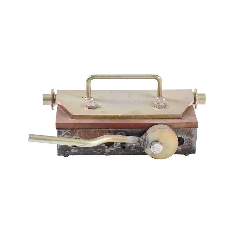
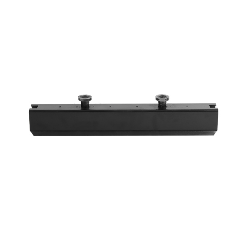
Thinner panels bring a production challenge, though: the formwork must sit accurately on the casting bed, and thin edges must be held to tight dimensional tolerances. This is where magnetic shuttering systems become part of the carbon fiber production workflow. A shuttering magnet with handle locks steel side forms to the magnetic casting bed without bolts or welding, and releases quickly when the panel is ready for demolding. The production crew can reposition formwork between pours in minutes instead of hours, which is essential when cycling thin architectural panels through the bed.
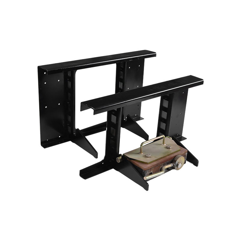 Magnetic Shuttering Magnet with Handle for Quick Formwork RepositioningThis reusable magnet with a handle locks steel formwork to the casting bed without bolts, enabling fast repositioning between pours—critical for efficient thin carbon-fiber panel production.View Product →
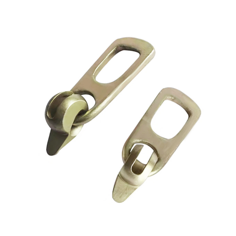
Carbon fiber also changes how precast pieces are lifted. Because fibers reduce early-age cracking, a panel can be stripped from the form earlier than a plain concrete panel of the same thickness. Lifting anchors placed in the wet concrete must hold position accurately during casting. An erection anchor mounted to the magnetic form face keeps the loop or threaded insert in the correct location, and the magnetic holding force prevents movement when the carbon-fiber mix is vibrated.
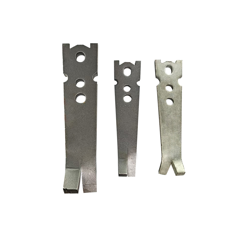 Durable Erection Anchor for Precast Concrete Lifting and PositioningEngineered for high load-bearing capacity and corrosion resistance, this anchor securely holds lifting loops or inserts during casting, ensuring accurate placement when panels are stripped early in carbon-fiber workflows.View Product →
For producers who already use magnetic formwork, the reusability of shuttering magnets matters more with fiber-reinforced mixes because the form setup cycle determines how many thin panels the plant can produce in a shift. Quick repositioning allows more pours per day, and that is where carbon fiber economics work in favor of the precaster.
One additional detail affects surface quality. Carbon fiber reinforced concrete has a more cohesive fresh state, so sharp edges and chamfers need careful definition. A plastic or steel chamfer profile inserted in the form gives the panel a crisp edge while protecting the thin fiber-rich surface from spalling during demolding. The same chamfer family used for architectural precast works well for carbon fiber panels and reduces edge repair labor.
Cost, Sustainability, and Long-Term Performance
Carbon fiber still costs more than steel fiber on a per-kilogram basis. Short chopped polyacrylonitrile-based carbon fiber is typically supplied in the range of $20 to $45 per kilogram, depending on tow size, surface treatment, and cut length. Steel fiber, in contrast, costs roughly $1 to $3 per kilogram. That price gap looks alarming until you compare the actual added cost per cubic meter: a 0.3% volume fraction of carbon fiber adds about 4.8 kg/m³, or roughly $100 to $215 per cubic meter. That is a real premium, but it buys a measurable increase in crack resistance and durability.
The lifecycle argument changes the picture significantly. A structure that needs major repair at year 10 because of freeze-thaw damage or chloride-induced corrosion will cost far more than the carbon fiber premium saved at the time of construction. Bridge deck overlays with carbon fiber routinely extend maintenance intervals because they control the reflective cracking that lets water reach the deck below. For a typical parking structure, the added first cost of carbon fiber is often recovered by deferring the first major overlay repair by 5 to 10 years.
Carbon fiber also has a sustainability advantage that owners increasingly evaluate. Because it improves flexural and tensile performance, engineers can reduce cross-section thickness in non-structural cladding panels, thin shells, and flat plate elements. A 20% to 30% section reduction means directly less cement demand, less aggregate extraction, and lower transport weight. In a comparative life-cycle assessment of a typical precast façade panel, cement reduction alone can cut the panel's embodied CO₂ by roughly 10% to 15%. Carbon fiber itself is energy-intensive to manufacture, so the net benefit depends on actual section savings, but it is a measurable and defensible gain when documented in the design phase.
For edge details in thin carbon fiber panels, using a precast concrete chamfer insert is one of the lowest-cost ways to protect the section. The chamfer removes the sharp 90-degree corner where spalling starts and creates a clean architectural line. When owners specify close visual tolerances, the chamfer also hides minor panel-to-panel alignment variation.
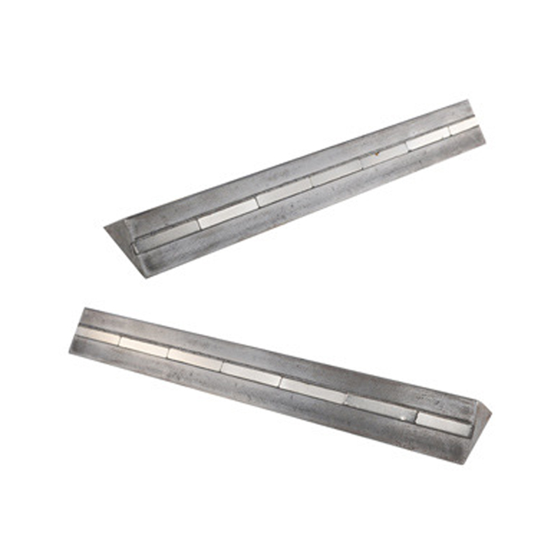 Magnetic Precast Concrete Chamfer Insert for Edge ProtectionThis magnetic device secures chamfer formwork firmly during pouring, removing sharp corners to prevent spalling and creating a clean architectural line—ideal for thin carbon-fiber panels with tight visual tolerances.View Product →
Frequently Asked Questions
Can carbon fiber replace rebar in structural concrete?
No. Carbon fiber reinforcement improves concrete's own tensile resistance, fracture energy, and crack control, but it does not provide the same tension capacity as steel rebar. In walls and slabs, carbon fiber grid can replace non-structural steel mesh where the only job is controlling shrinkage cracks. But for beams, columns, and other load-bearing members, structural reinforcement must be designed by a structural engineer, and carbon fiber is a supplement, not a substitute.
What is the typical carbon fiber dosage in concrete?
Most commercial mixes use 0.2% to 0.5% fiber by volume, which equals about 3 to 8 kg per cubic meter. Higher dosages up to 1.0% by volume are possible but require additional water-reducing admixtures and longer mixing cycles. The SHRP research program used 1.0% of cement weight, approximately 4 kg/m³ for a typical mix, and recorded strong durability improvements at that level.
What are the main disadvantages of carbon fiber reinforced concrete?
The three biggest concerns are cost, workability, and dispersion. Carbon fiber is significantly more expensive than steel or polypropylene fiber. Adding carbon fiber reduces slump and requires mixing adjustments. If not properly dispersed, the fiber clumps and creates visible dark spots that also form weak points. Using pre-dispersed fiber products, extending dry-mix time, and doing trial batches solves most of these issues.
Does carbon fiber improve freeze-thaw durability?
Yes. In the SHRP-92-605 report, concrete with carbon fiber at 1.0% of cement weight showed an 85% improvement in strength compared with a plain concrete control, along with better freeze-thaw resistance. Even at lower dosages, carbon fiber reduces the microcracking that lets water penetrate the paste, which is the main mechanism behind freeze-thaw damage.
How does carbon fiber compare with steel fiber in concrete?
Carbon fiber is corrosion-immune, lighter, and roughly 2 to 4 times the tensile strength of common steel fiber, making it well suited for thin panels that will see chlorides. Steel fiber is cheaper, easier to mix, and provides excellent post-crack toughness where large deflections are expected. Carbon fiber controls fine cracks better; steel fiber controls large openings better.