English
 Español
 русский
 日本語
 عربى

Content
- 1 The Short Answer: Capacity Is the Lower of Two Numbers
- 2 Reading the Load Table: The Details That Set the Real Load Class
- 3 Erection Anchors, Two-Hole Anchors and Lifting Clutches
- 4 Concrete Strength at Lifting: The Footnote Behind Most Failures
- 5 Edge Distance, Spacing and Panel Thickness
- 6 Fixing the Anchor in the Mould Without Moving It
- 7 Failure Modes and What Triggers Them
- 8 Inspection, Reuse and Storage
- 9 What to Confirm Before Placing an Order
- 10 Frequently Asked Questions About Lifting Anchors for Concrete
- 10.1 What exactly is a lifting anchor for concrete?
- 10.2 Which load class do I need for a 5 t panel?
- 10.3 How deep does a lifting anchor need to be embedded?
- 10.4 Can concrete be lifted before it reaches 28-day strength?
- 10.5 How close to the edge can an anchor be placed?
- 10.6 Are lifting anchors reusable?
- 10.7 What happens when a clutch is worn?
- 10.8 Does the pull angle really change the capacity?
- 10.9 How many anchors should a panel have?
- 10.10 What should I send a supplier for an accurate recommendation?
A crew in a precast yard is about to lift a 6.4 t wall panel. Four spherical-head anchors are cast into the panel, so the arithmetic looks easy: 6.4 divided by four is 1.6 t per anchor, and the 2.5 t anchors in the rack should be more than enough. The panel rises 300 mm and one anchor pulls a cone of concrete out of the face. The anchor itself is undamaged. The concrete around it was not.
That gap between the number printed on the anchor and the load the panel actually carries is where most lifting problems live. A 2.5 t erection anchor is only 2.5 t under a defined set of conditions: a minimum concrete strength at the moment of the lift, a minimum edge distance, a minimum spacing, a defined pull direction, and a clutch that seats on the head correctly. Change one condition and the real capacity can sit far below the label.
What follows is a practical walk-through of how lifting anchors for concrete are chosen, how load tables are meant to be read, which details get missed in the yard, and what to include in an enquiry when you buy anchors, clutches and the magnetic accessories that hold them in the mould.
The Short Answer: Capacity Is the Lower of Two Numbers
The capacity of a lifting anchor is decided by whichever part fails first, the steel anchor or the concrete around it.
- In strong, thick, well-confined concrete, the anchor steel usually governs. The head either holds or it does not.
- In young concrete, thin panels, or anchors set close to a free edge, the concrete governs. The anchor survives the lift, but it leaves with a cone of the panel attached.
Practically, the usable load of a cast-in lifting anchor is always the smaller of the steel capacity and the concrete breakout capacity, evaluated at the concrete strength that exists when the crane hook tightens. Everything else in a catalogue is a footnote to that sentence.
Three questions decide almost every selection, and they are worth answering in writing before an anchor is ordered:
- What does the element weigh, and how unevenly will the anchors share that weight?
- What concrete strength will the panel have at the moment of lifting, not at 28 days?
- In which direction will the load act, and how much dynamic amplification comes with taking up the slack?
An anchor sized against element weight alone answers only the first question. That is why two plants can buy the same 5 t anchor and get very different results from it.
Reading the Load Table: The Details That Set the Real Load Class
Most enquiries start with a weight and stop at a load class. The differences between suppliers sit in the assumptions underneath the headline figure, and those assumptions are rarely printed on a quotation. One catalogue may state a minimum concrete strength of 15 N/mm2 at the lift, another may assume 20 N/mm2. One may assume a purely axial pull, another may allow a small angle. Comparing bare load classes between two brands is therefore an unreliable shortcut.
| Load class | Typical anchor length | Typical minimum panel thickness | Typical element |
|---|---|---|---|
| 1.3 t | 90 to 120 mm | 100 to 120 mm | Thin walls, stair flights, small columns |
| 2.5 t | 130 to 170 mm | 120 to 140 mm | Wall panels, beams, columns |
| 5.0 t | 180 to 230 mm | 150 to 180 mm | Large wall panels, T-beams |
| 10 t | 250 to 320 mm | 200 to 250 mm | Heavy beams, bridge elements |
| 20 t | 350 to 470 mm | 300 mm and above | Girders, massive precast units |
Behind that table sit five more figures that decide whether the chosen class holds up in practice. The minimum concrete strength at lift, the minimum edge distance, the minimum anchor spacing, the reduction factor for a pull that is not axial, and the dynamic factor applied to the lift. Ask for all five in writing. A supplier who cannot produce them in a single document is a supplier who will leave the calculation to you.
One more habit worth adopting: design as though only two anchors carry the load, even when four are cast in. Precast panels are rarely perfectly flat, and a slightly bowed panel transfers most of the load into two anchors while the other two stay almost idle. This is standard practice in many precast yards and it is the cheapest insurance available.
Erection Anchors, Two-Hole Anchors and Lifting Clutches
Three components form a cast-in lifting system, and each one solves a different part of the problem.
Spherical-head erection anchors for straight vertical picks
A spherical-head erection anchor is cast into the element with its round head sitting in a shallow recess at the concrete surface. A ring clutch drops over the head, engages mechanically, and pulls along the anchor axis. This is the fastest and most predictable pick in a precast plant, which is why it is the default choice for wall panels, columns and beams that are lifted vertically out of the bed.
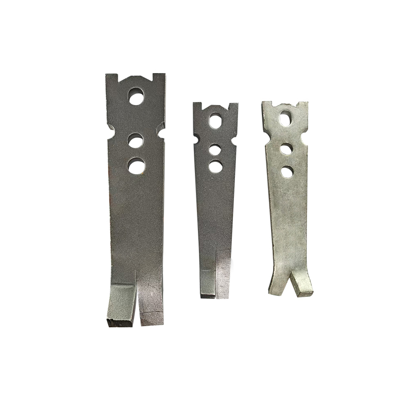 Erection AnchorThe Erection Anchor is a specialized tool engineered for lifting and securing precast concrete elements during transportation, installation, and assembly. Produced by ...View Product →
Two-hole anchors for tilting, turning and slinging
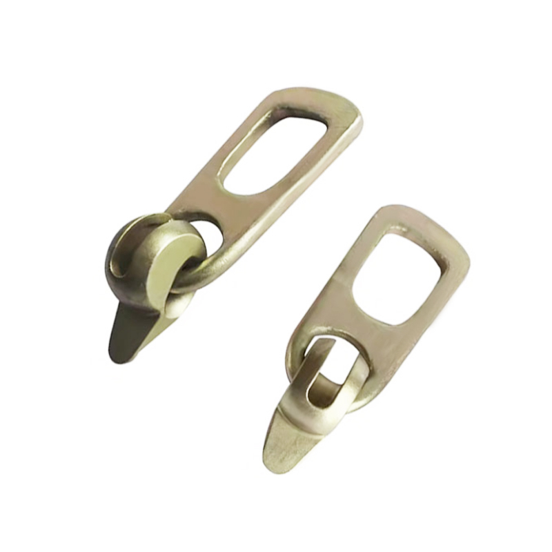
A two-hole anchor is a flat steel plate with two openings, cast in flush or slightly recessed. A wire rope sling or shackle passes through the plate, which allows the element to rotate through 90 degrees without forcing the load into a head that was designed for an axial pull. When a panel must be tilted from flat to vertical, or turned over for finishing, a two-hole anchor gives the flexibility that a spherical-head anchor cannot. It also spreads the load over a longer welded or forged plate, which suits thicker, heavier elements.
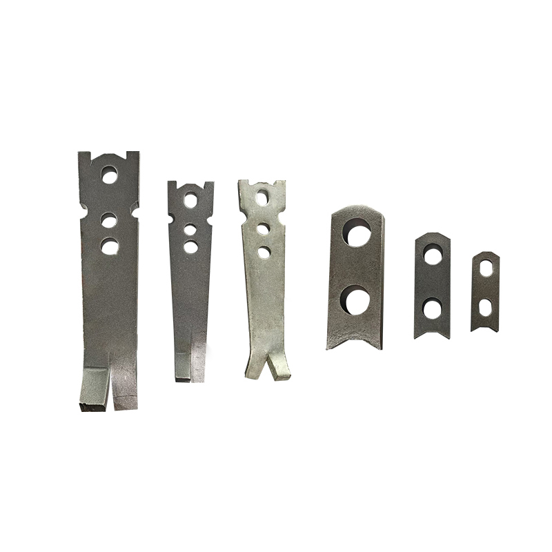 Two Hole AnchorProduct Short DescriptionView Product →
Lifting clutches: the reusable half that wears out
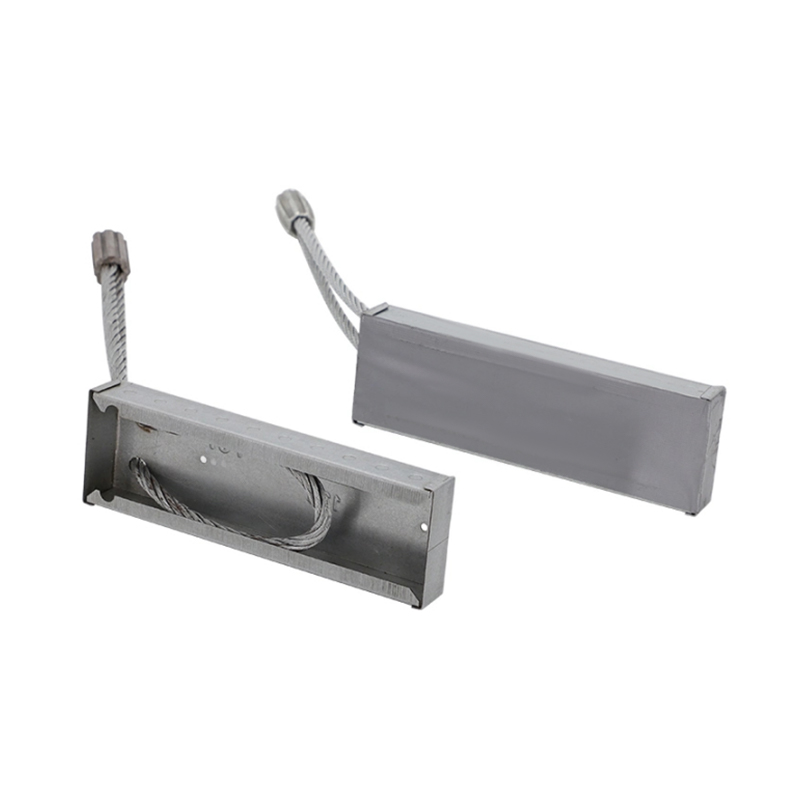
Anchors stay in the concrete. Clutches stay in the yard and go back to work hundreds of times. That makes the clutch the moving part in the system, and moving parts wear. Engagement depth, spring force, pin condition and any deformation at the load-bearing radius all change the load path between the crane hook and the concrete. A clutch that engages only partially concentrates the load on a small area of the head, and the failure it produces looks like an anchor defect even though the anchor was never loaded as designed.
Concrete Strength at Lifting: The Footnote Behind Most Failures
Here is the comparison that changes how most people read a load table. Concrete breakout capacity scales roughly with the square root of compressive strength, the relationship used in concrete breakout design. Drop the concrete from 30 N/mm2 to 15 N/mm2 at the moment of the lift and the concrete-controlled capacity does not halve, but it does fall to about 71 percent of the table value (the square root of 0.5). On a nominal 2.5 t anchor that leaves roughly 1.77 t of real capacity, for the same anchor, in the same panel, with the same crane.
Precast plants lift early, sometimes within 10 to 14 hours of casting, and that is normal and acceptable as long as the strength condition in the load table is met. The problem is that a single curing regime does not produce a single strength. A steam-cured panel in the middle of a battery mould can reach 25 to 35 N/mm2 overnight, while a panel cast at the same time in a cold corner of the yard may sit at 8 to 12 N/mm2. Same mix, same shift, very different lifting capacity.
Cubes or cylinders cured beside the element are the only honest measure, and they should be tested at the time of lift rather than at 28 days. A useful working habit is to mark the required lifting strength on the mould and to hold the crane until the sample passes it, no matter how the shift is running. Lifting a panel an hour early is the most common route to a concrete cone failure, and it leaves an anchor that looks brand new next to a crater in the face of the element.
Edge Distance, Spacing and Panel Thickness
Every anchor table publishes three layout numbers, and the edge distance is the one that gets argued with, usually because the anchor looks tidier closer to the corner.
For a 5 t class anchor, typical published minimum edge distances fall in the 150 to 250 mm range, and they grow with the load class because the concrete cone that resists the pull needs room to develop. A pull acting parallel to a free edge is the worst orientation in the whole system, and catalogues normally either apply a heavy reduction or refuse the arrangement outright. If the element geometry does not allow the minimum edge distance, the lifting arrangement has to change: more anchors at a lower class, a different anchor position, or a lifting frame that keeps the load axial.
Spacing works the same way. Two anchors set 300 mm apart do not deliver twice the capacity of one anchor, because their concrete cones overlap and the same volume of concrete resists both loads. Typical tables require a minimum spacing expressed either in millimetres per load class or as a multiple of the anchor length, and the requirement becomes tighter as the load class increases.
Panel thickness follows from the anchor length plus bottom cover, typically 20 to 30 mm. Cutting an anchor shorter to fit a thinner panel removes exactly the embedment that provides the capacity. When a 120 mm wall needs to be lifted, the answer is a short anchor designed for thin elements, not a standard anchor with 60 mm ground off the end.
Fixing the Anchor in the Mould Without Moving It
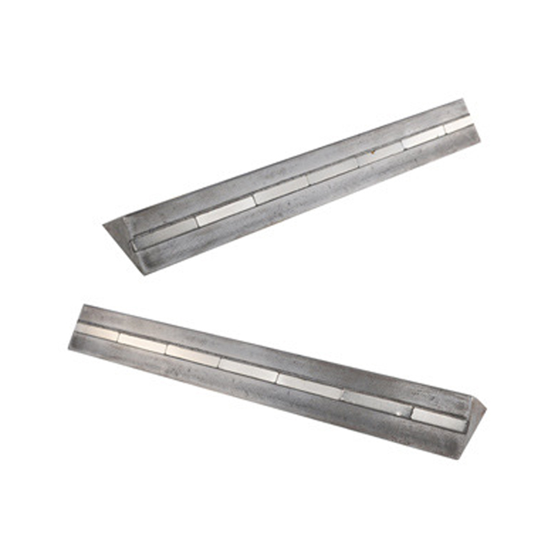
An anchor that shifts 15 mm during vibration is a different anchor as far as the concrete is concerned, because the measured edge distance is no longer the one on the drawing. Magnetic fixing solves this cleanly. Insert magnets hold the shank or plate of the lifting anchor hard against the mould face, so internal vibrators pass over them without dragging the anchor out of position. Positional tolerance in most precast work is stated as plus or minus 5 to 10 mm, and it is verified after casting rather than assumed.
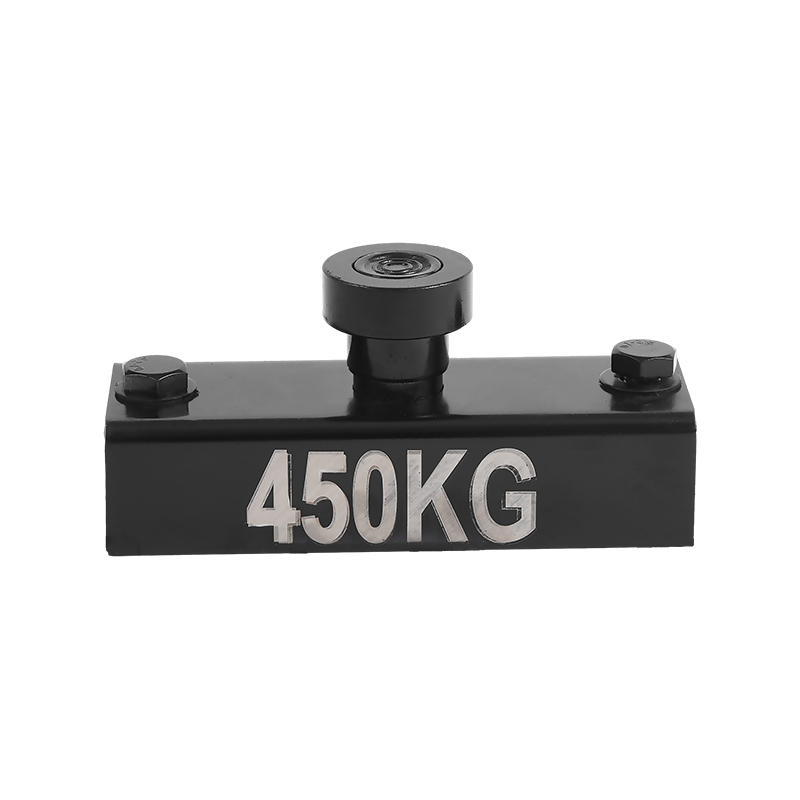
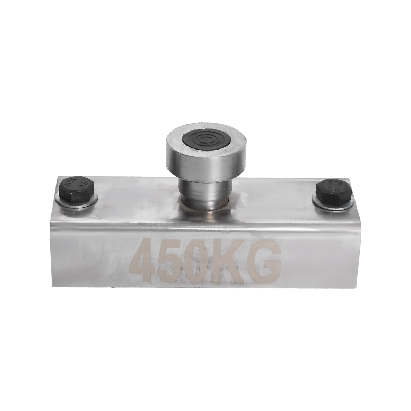
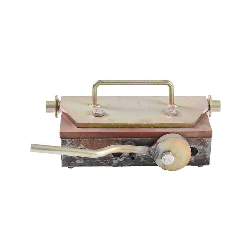
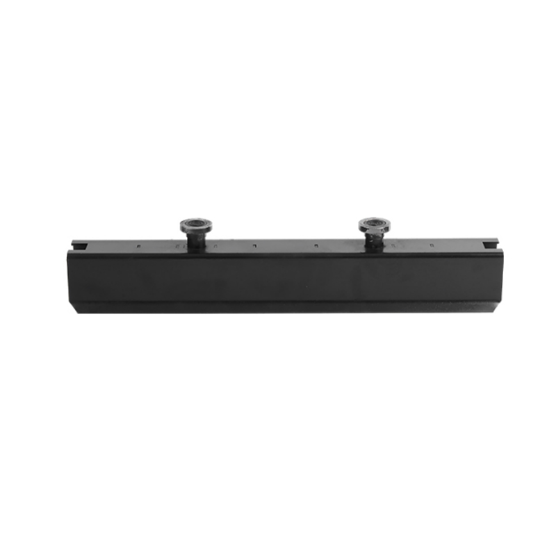
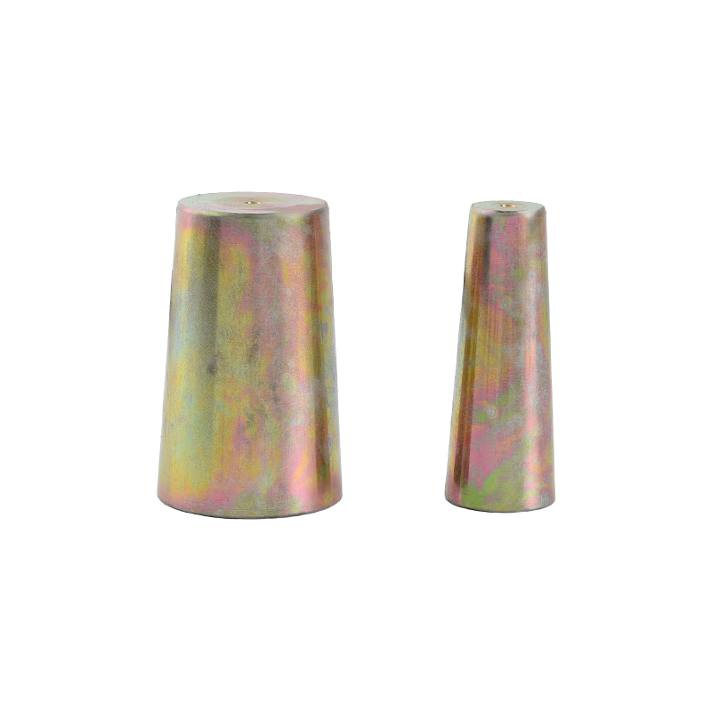 Insert magnetsThe insert magnet is used in the precast concrete production structures to form free spaces in the work-pieces to fix the concrete inserts. Insert magnets are used in ...View Product →
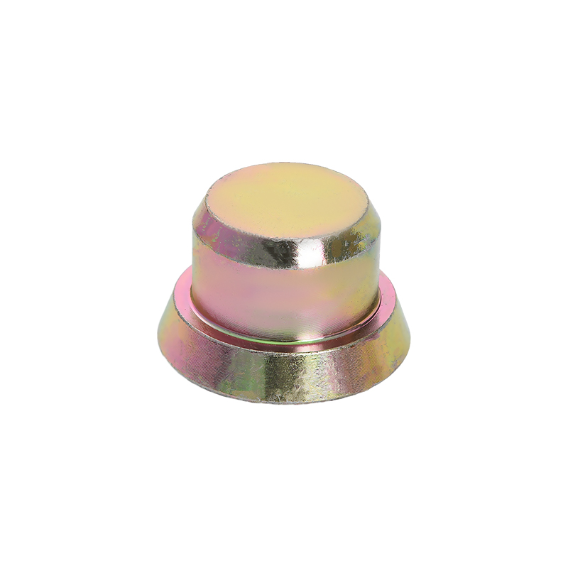
The head recess deserves the same attention. If concrete paste runs into the recess during the pour, the clutch cannot seat to full depth, and the load lands on a fraction of the head. Check that the recess former sits tight against the head, clean it every cycle, and reject any anchor whose recess is filled with hardened concrete rather than trying to chip it out on the bed. For a closer look at the mechanics, there is a useful explanation of how insert magnets hold lifting hardware in precast moulds that covers positioning, magnet strength and release.
Failure Modes and What Triggers Them
| Failure mode | Typical trigger | Control |
|---|---|---|
| Concrete cone breakout | Lifting below the stated minimum strength, or an anchor set inside the minimum edge distance | Test cubes at the time of lift; mark the minimum edge distance on the mould drawing |
| Anchor steel fracture | Overload, wrong load class, or an oblique pull the table does not cover | Size on real element weight with uneven sharing and dynamic factors; apply angle reductions |
| Pull-out with head damage | An undersized anchor, or an anchor cut short to fit a thin panel | Keep full embedment; specify a thin-panel anchor instead of shortening a standard one |
| Clutch release under load | A worn clutch, a head that is not fully seated, or concrete in the head recess | Inspect clutches on a fixed cycle; clean the recess; never use a partly engaged clutch |
| Anchor out of position | An insert magnet shifted by vibration, or a mould changed without updating the position | Fix magnets firmly against the form face and measure the position after the pour |
| Spalling around the recess | Sudden take-up of load with no pre-tension | Take up the slack slowly before the panel leaves the casting bed |
Notice how few of these failures are caused by the anchor steel itself. Most of them sit in the concrete, in the layout, or in the reusable hardware, which means most of them are preventable with paperwork and a checklist rather than with a heavier anchor.
Inspection, Reuse and Storage
Cast-in anchors are single-use items. Nothing about an embedded anchor is designed for a second pour, and an anchor that has been pulled to its limit should not be trusted again even if it looks unchanged.
Clutches, slings, swivels and shackles are reusable, which is exactly why they need a written inspection routine rather than a glance before the shift. Check the engagement depth against the new-part dimension, look for a bent or sticking pin, a tired spring, cracks at the load-bearing radius, and paint thick enough to hide distortion. Replace on a fixed wear limit instead of after a failure, and record the replacement date on the unit.
Storage is a small detail with a large effect. Keep anchors dry and in their original load-class groups, because a mixed box is one of the simplest ways to put a 2.5 t anchor where a 5 t anchor was intended. Light surface rust on a head is not automatically a rejection, but it should be cleaned and checked before a clutch goes on. Anything bent, cracked or deformed goes in the scrap bin, not back on the rack.
What to Confirm Before Placing an Order
A lifting anchor enquiry that answers the following points usually comes back with a usable load class on the first reply, instead of three rounds of questions about panel thickness.
- Element weight, plus the allowance for uneven sharing between anchors.
- Concrete strength at the moment of lifting, taken from the production schedule rather than the 28-day figure.
- Minimum edge distance and spacing available on the real panel, not on an idealised drawing.
- Anchor length against panel thickness, including bottom cover.
- Pull direction during lifting, turning and erection, with the angle factors applied.
- Head diameter and the exact clutch model that fits it, as a cross-reference on the order.
- The load table in writing, including strength and angle reductions.
- Dimensional drawings with tolerances, and whether the recess former is supplied with the anchor.
- Delivery time for samples and for the batch, and how anchors are packed by load class.
- Availability of replacement clutches and spare parts from the same source.
Plants that run several element families usually find it cheaper to standardise on two or three load classes and keep the matching clutches in the same caddy. Fewer combinations on the bed means fewer chances to fit the wrong anchor on a Friday afternoon.
Frequently Asked Questions About Lifting Anchors for Concrete
What exactly is a lifting anchor for concrete?
It is a cast-in steel component embedded in a precast element so a crane can pick, turn, transport and erect that element. The two common shapes are spherical-head erection anchors, which are engaged by a ring clutch, and two-hole anchors, which accept a wire rope sling or shackle. Both work by transferring the hook load into a defined volume of concrete.
Which load class do I need for a 5 t panel?
If four anchors are cast in and the design allows for uneven sharing, the working figure is 5 t divided by two, which is 2.5 t per anchor before dynamic and angle factors. That makes a 2.5 t class the absolute floor and a 5 t class the more forgiving choice, especially when the panel will be tilted or the pull will not be perfectly axial. Confirm against the supplier's load table for the final decision.
How deep does a lifting anchor need to be embedded?
Whatever the load table states for that class. Typical catalogue lengths run from roughly 90 to 120 mm for a 1.3 t anchor up to 350 to 470 mm for a 20 t anchor. Embedment depth sets both the concrete capacity and the minimum panel thickness, so it is not a dimension to adjust on site.
Can concrete be lifted before it reaches 28-day strength?
Yes. Precast elements are normally stripped and lifted within a day, and the load tables are written for that reality. The condition is that the concrete has reached the minimum strength stated for the anchor at the time of the lift, verified with cubes or cylinders cured beside the element. The 28-day figure has almost nothing to do with the lifting decision.
How close to the edge can an anchor be placed?
Never closer than the published minimum, and that minimum rises with the load class. For a 5 t class anchor, typical published minimum edge distances sit between 150 and 250 mm. If the panel geometry will not allow it, the lifting arrangement must change rather than the edge distance, because a pull parallel to a free edge is the least forgiving case in the whole system.
Are lifting anchors reusable?
The anchors themselves are not, because they are cast into the concrete and stay there. The clutches, shackles and slings are reusable, and they are the parts that need a documented inspection cycle and replacement on a wear limit rather than after a failure.
What happens when a clutch is worn?
Engagement depth drops, load concentrates on a smaller area of the head, and the clutch can release while the panel is in the air. Compare the engagement dimension with the new-part figure at every inspection, and treat any clutch that fails the check as scrap.
Does the pull angle really change the capacity?
It does, and often by more than expected. Capacity is highest when the load acts along the anchor axis. As the pull rotates away from that axis, capacity falls and most catalogues either publish reduction factors or require a larger load class. Unless a lift is certain to be axial, angle factors belong in the calculation.
How many anchors should a panel have?
Two is the usual minimum, and four is common on larger or more flexible elements, because it gives the crane more control over the panel as it leaves the bed. More anchors do not divide the load evenly, so the design normally allows for a share of the load being carried by fewer anchors than the total number cast in.
What should I send a supplier for an accurate recommendation?
A panel drawing with thickness, the element weight, the concrete strength at lift, the available edge distances, the pull direction, and the number of clutches required. That single package is usually enough to receive a load class recommendation and a matching clutch reference without a round of guessing.
Two things carry the risk in a precast lift, and neither of them is the number printed on the anchor box. The concrete has to be strong enough on the day, and the clutch has to engage the head the way it did when it was new. Get those two right and a 2.5 t anchor will do exactly what the table says it will do.
The practical routine is short. Confirm the concrete strength at the moment of lift rather than at 28 days. Keep the anchor inside its published edge distance and spacing. Hold the anchor in the mould with a magnet that will not move under vibration. Log clutch wear against a fixed figure. Standardise on a small number of load classes so the bed cannot be loaded with the wrong one.
Do those five things and the load table becomes a usable document instead of a marketing sheet. Skip them and the anchor will still look perfect after the lift, sitting in a crater that nobody expected.