English
 Español
 русский
 日本語
日本語
 عربى
عربى
Content
- 1 What Is a Shuttering Magnet and Where Is It Used
- 2 The Physics Behind the Switchable Feature
- 3 Step-by-Step: How the Switchable Feature Works in Practice
- 4 Shuttering Magnet Force Ratings and Specifications
- 5 Types of Shuttering Magnets by Activation Mechanism
- 6 Key Design Parameters That Determine How Well the Switchable Feature Performs
- 7 Shuttering Magnets Under Concrete Vibration: What Happens Internally
- 8 Shuttering Magnets vs. Other Formwork Fastening Methods
- 9 Maintaining the Switchable Feature: Practical Maintenance Guide
- 10 How to Select the Right Shuttering Magnet for Your Precast Application
- 11 Trends in Shuttering Magnet Technology
- 12 FAQ: Shuttering Magnet Switchable Feature
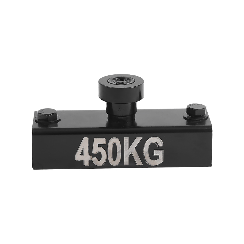
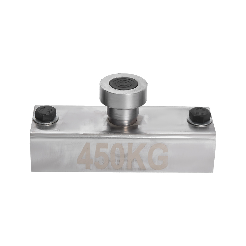
A shuttering magnet works by using a rotating internal magnet assembly to switch between an active magnetic state and a near-zero external flux state. When switched ON, its magnetic field clamps ferromagnetic formwork with forces ranging from 500 N to over 3,500 N. When switched OFF, the internal magnets cancel each other out, and the unit releases cleanly with a simple 180-degree key rotation — no electricity required at any point.
3,500 N Peak holding force (heavy-duty models)
180° Key rotation to switch states
0 W Electricity consumed during operation
What Is a Shuttering Magnet and Where Is It Used
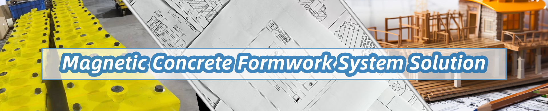
A shuttering magnet — sometimes called a precast magnet, formwork magnet, or casting magnet — is a switchable permanent magnet device used in precast concrete production. It holds steel shuttering profiles (side rails, inserts, blockouts) flat against the steel casting bed during concrete pouring and vibration, then releases them cleanly once the concrete has cured.
Unlike traditional bolt-down or clamp methods, a shuttering magnet requires no drilling, no welding, and no fasteners. A worker positions the formwork element, presses the magnet into contact with the steel bed using a simple lever or key, and the magnet holds the profile in place while concrete is cast around it.
These devices are found in plants producing hollow-core slabs, double tees, wall panels, columns, beams, and other precast structural elements. Leading European precast producers switched to magnetic shuttering systems beginning in the early 2000s, and the technology has since spread globally as precast concrete output has expanded. According to the European Precast Concrete Association, European precast concrete production exceeded 200 million cubic meters annually by the early 2020s, and magnetic shuttering tools are now standard in most automated or semi-automated plants in the region.
Industry Note
The shift from mechanical clamps to shuttering magnets in precast plants is documented as reducing formwork setup time by 30–50% on typical panel lines. (Source: Precast/Prestressed Concrete Institute, 2019 technology survey)
Core Advantage
No electricity. No drilling. Full holding power from permanent magnets alone — switched ON and OFF mechanically.
The Physics Behind the Switchable Feature
To understand how a shuttering magnet's switchable feature works, you need to understand magnetic flux path manipulation. Every permanent magnet creates a field — a loop of magnetic flux that travels from north pole to south pole. The key engineering insight behind switchable permanent magnets is that this flux can be redirected internally so that it circulates entirely within the magnet housing rather than extending outward to grip an external surface.
Two-Magnet Opposing Configuration
Most shuttering magnets use a two-magnet system with one fixed magnet and one rotating magnet. In the OFF state, the rotating magnet is positioned so its poles are aligned opposite to the fixed magnet — north against north, south against south. The flux from each magnet cancels internally, and virtually no field escapes from the bottom face. On a steel casting bed, the magnet sits with almost zero attraction — it can be slid and repositioned by hand.
When the operator rotates the inner magnet 180 degrees using a key or lever, the poles align north-to-south across the two magnets. Now the flux path runs out through the bottom face, through the steel bed, and back — this is the ON state. The shuttering magnet grips the bed with its full rated force, measured in Newtons or sometimes kilogram-force (kgf).
The magnetic material used is almost universally neodymium iron boron (NdFeB), grade N42 or higher, for its extremely high energy product (measured in MGOe — megagauss-oersteds). NdFeB magnets produce stronger fields per unit volume than any other commercially available permanent magnet material. A typical shuttering magnet housing might contain NdFeB blocks with an energy product of 42–52 MGOe, which is what allows a compact unit to deliver over 1,000 N of holding force.
The Role of the Mild Steel Housing
The outer housing of a shuttering magnet is machined from mild steel, which serves as the magnetic circuit's return path. Steel has high magnetic permeability — it channels flux efficiently. The housing is precision-machined so that in the ON state, the gap between the bottom face and the steel casting bed is minimized, typically less than 0.1 mm. Every fraction of a millimeter of air gap significantly reduces holding force. A 1 mm air gap can reduce force by 60–80% compared to full contact, which is why the contact face of the magnet must be kept clean and flat.
Halbach Array Variants
Some advanced shuttering magnets use a Halbach array configuration — a spatial arrangement of permanent magnets that concentrates the magnetic flux on one side of the assembly. Halbach arrangements were first described by physicist Klaus Halbach in 1980 for use in particle accelerators (source: Klaus Halbach, "Design of Permanent Multipole Magnets," Nuclear Instruments and Methods, 1980). In a shuttering magnet context, a Halbach-inspired configuration means the bottom face has an intensified field while the top face has a near-zero field, improving both holding force and operator safety.
Step-by-Step: How the Switchable Feature Works in Practice
The switchable feature of a shuttering magnet is straightforward in operation but relies on precise internal geometry. Here is exactly what happens at each stage:
1
Positioning (OFF State)
The shuttering magnet is in its OFF state. The internal rotor magnet is oriented so its poles oppose the fixed magnet. External flux is near zero — typically less than 5% of rated force leaks outward. The magnet body can be lifted, carried, and placed by hand on the steel casting bed with minimal resistance.
2
Activation
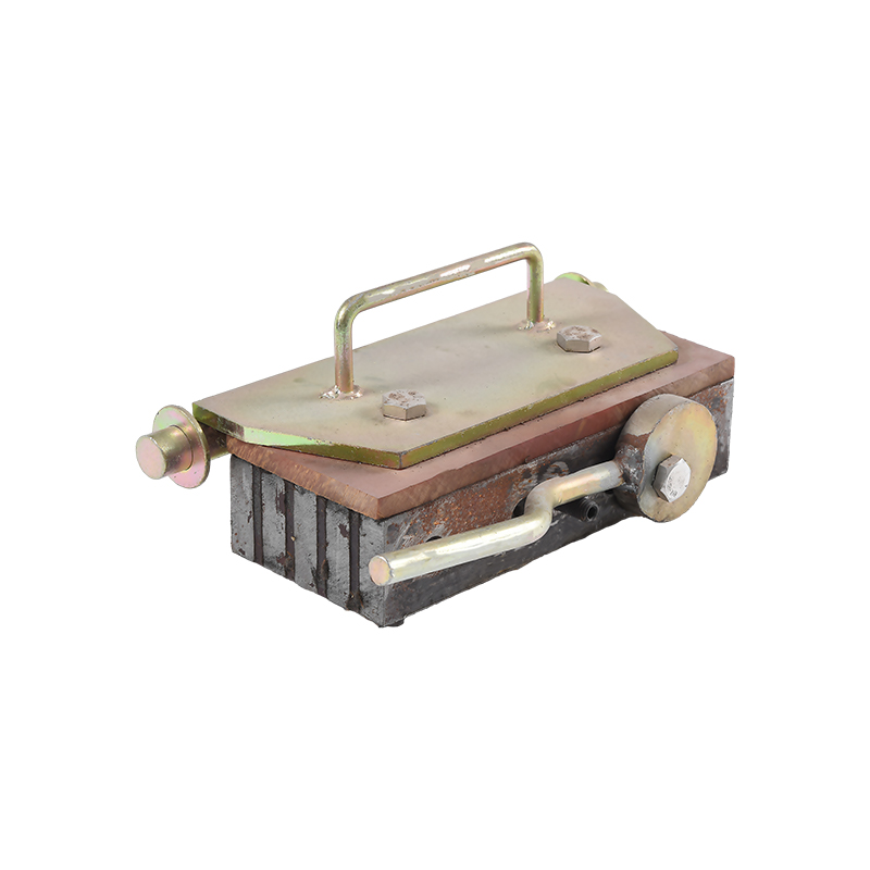
The operator inserts a T-key or lever into the keyhole on the top of the magnet body and rotates 180 degrees. This mechanically rotates the internal NdFeB rotor to the aligned position. The flux path switches from internal cancellation to full external projection through the bottom face.
3
Clamping (ON State)
In the ON state, the shuttering magnet grips the steel casting table with its full rated holding force. For a 1,000 N unit, that is approximately 102 kgf — enough to keep steel shuttering profiles firmly in place during high-frequency concrete vibration (typically 50–200 Hz at amplitudes of 0.5–3 mm). The magnet does not consume any electricity during this period.
4
Release
After concrete cures, the operator rotates the key again — another 180 degrees — returning the rotor to the opposing position. Force drops to near zero. The magnet can then be pried off the bed (since residual surface friction still exists) using an integral lever or a separate de-activation tool. Many units include a built-in lever arm that provides mechanical advantage for this step.
5
Repositioning for the Next Cast
Once released, the shuttering magnet is repositioned for the next formwork layout. In fully automated precast plants with robotic formwork setters, this step is handled by a robot arm using solenoid-actuated magnets — but the underlying physics and switchable principle remain the same as the manual version.
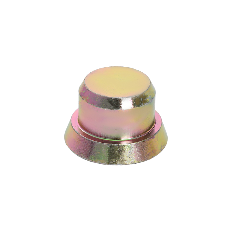
Shuttering Magnet Force Ratings and Specifications
Shuttering magnets are available in a wide range of holding force ratings to match different formwork loads. The table below summarizes common force classes, typical housing dimensions, and typical application scenarios.
| Force Rating | Approx. kgf | Typical Body Length | Common Applications |
|---|---|---|---|
| 500 N | ~51 kgf | 70–80 mm | Thin panel profiles, small inserts, decorative elements |
| 1,000 N | ~102 kgf | 100–120 mm | Standard wall panels, floor slabs, general shuttering |
| 1,500 N | ~153 kgf | 130–150 mm | Heavy shuttering profiles, staircase elements, balconies |
| 2,000 N | ~204 kgf | 160–180 mm | Beam and column forms, large blockout frames |
| 3,500 N+ | ~357+ kgf | 200–250 mm | Heavy structural elements, tunnel lining forms, bridge segments |
Force ratings are typically measured on a clean, flat, low-carbon steel plate of 10 mm or greater thickness. Thinner steel beds — or beds with surface coatings, rust, or concrete residue — reduce effective force significantly. This is why precast plant maintenance protocols consistently require cleaning both the magnet contact face and the steel bed surface before each production cycle.
Types of Shuttering Magnets by Activation Mechanism
Not all shuttering magnets switch the same way. While the underlying physics is the same, the mechanical interface for switching varies significantly between product lines:
KEY
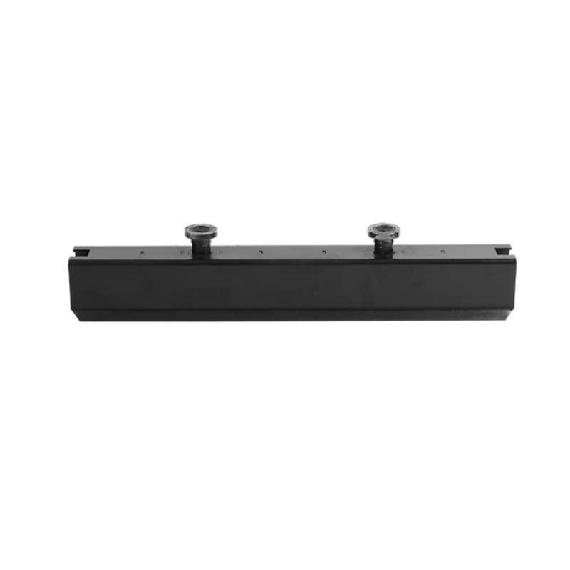
Key-Activated Rotary Magnets
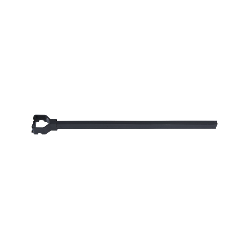
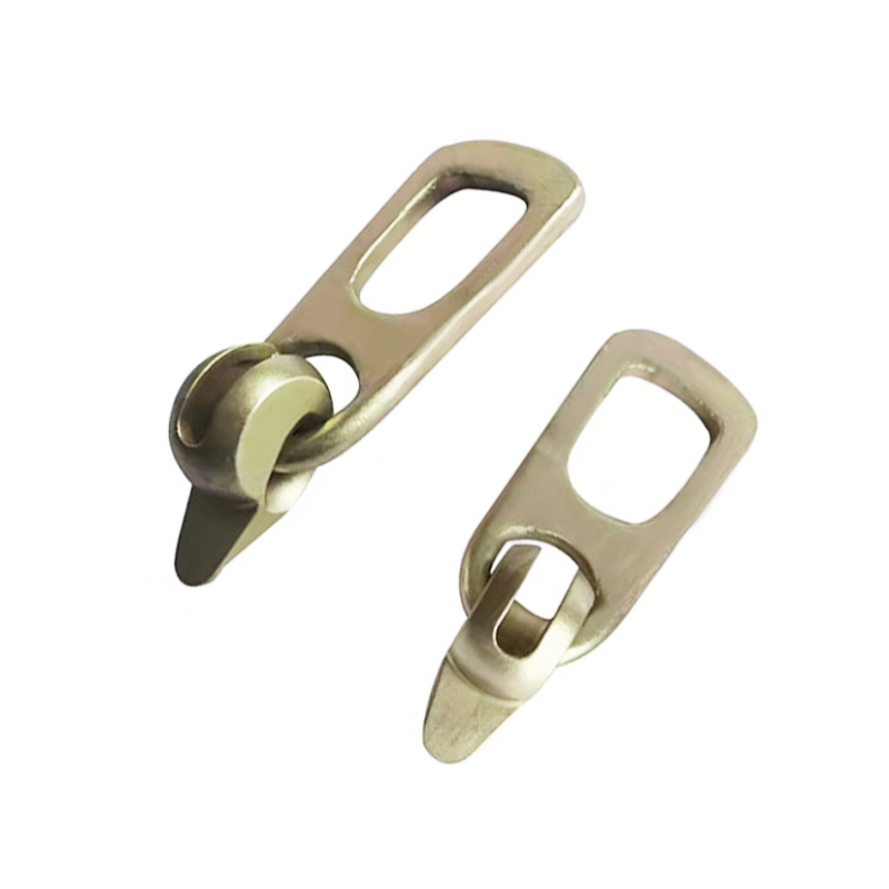
The most common type. A T-shaped or hex key is inserted into a port on top of the magnet and rotated 180 degrees. Simple, low-cost, and highly reliable. Requires the operator to carry a dedicated key, which is sometimes tethered to the magnet itself. Units from manufacturers such as Assfalg (Germany) and Fidbox (Italy) have used this mechanism for over 20 years.
LVR
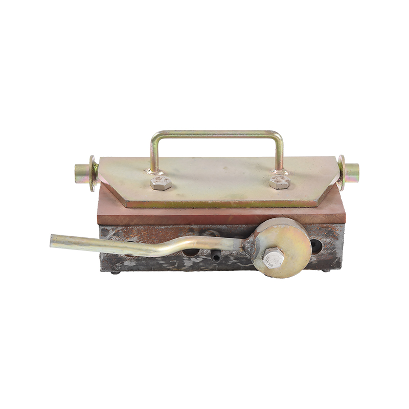
Lever-Activated Magnets
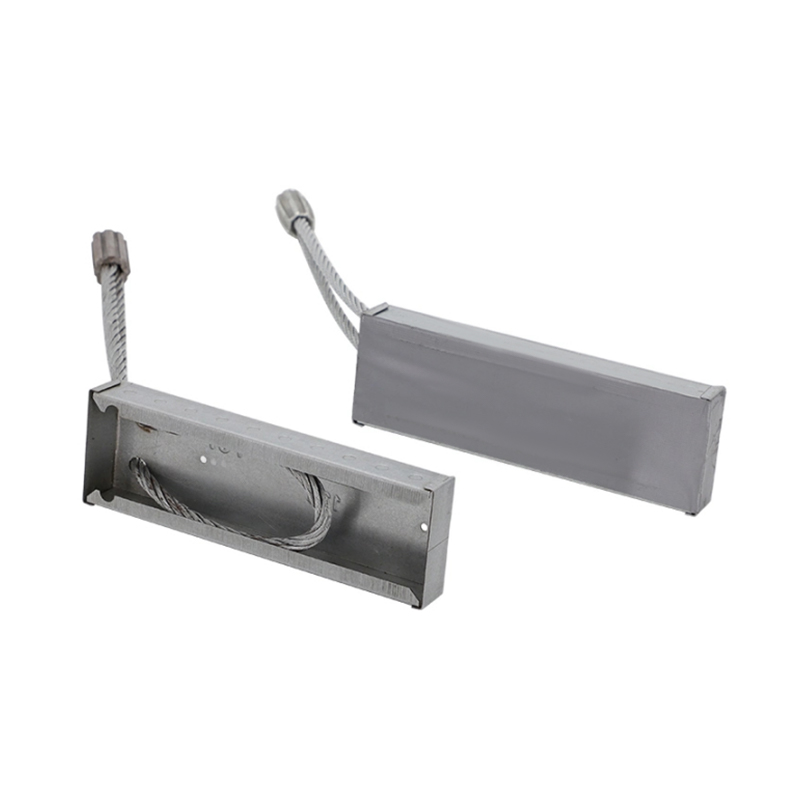
A built-in lever arm rotates the internal magnet and simultaneously provides mechanical advantage for lifting the magnet off the bed during release. This is the dominant design for heavy-duty units (2,000 N+), where the release force would otherwise be impractical to apply by hand. The lever also doubles as a carry handle during repositioning.
AUTO
Solenoid-Assisted Auto-Release Magnets
Used in fully automated precast carousels and robot-assisted lines. A small solenoid coil provides a brief pulse of opposing electromagnetic flux to overcome the mechanical friction of the rotor, allowing a robot or actuator to release the magnet without manual key operation. The holding force during casting remains purely from the permanent magnet — electricity is only used for the switching pulse.
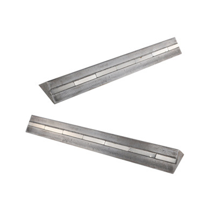
BOX
Box Magnets (Combination Frame Magnets)
These are elongated shuttering magnet assemblies with multiple magnetic poles along their length, designed to hold long shuttering rails over spans of 600–1,500 mm. Multiple magnetic cores in a single housing share a common switching mechanism. A single lever action activates all poles simultaneously, maintaining consistent holding force across the entire profile length.
Key Design Parameters That Determine How Well the Switchable Feature Performs
The quality of the switchable feature in any shuttering magnet depends on several engineering parameters. Understanding these helps precast producers select the right product and maintain it correctly:
Internal Magnet Grade
Higher NdFeB grades (N45, N50, N52) produce greater energy density. A grade N52 NdFeB magnet has a maximum energy product of approximately 52 MGOe, compared to 42 MGOe for N42. This directly translates to higher holding force per unit volume, allowing more compact housings for a given force rating. However, N52 grade is more brittle and slightly less corrosion-resistant, requiring better housing seal design.
Rotor Bearing Precision
The rotating inner magnet must turn smoothly to ensure reliable switching. Worn or corroded bearings increase switching torque, making it harder for operators to activate and release the unit. Quality shuttering magnets use sealed stainless steel bearings with rated cycle lives often specified at 100,000+ switching cycles. Below-spec bearings are the most common point of mechanical failure in used shuttering magnets.
Housing Material and Geometry
The low-carbon steel housing channels magnetic flux. Its wall thickness, geometry, and the precision of the machined contact face all affect how efficiently flux is delivered to the external surface. Contact face flatness tolerances are typically specified at 0.05 mm or better. Any warping or pitting from impact damage increases the effective air gap and reduces holding force.
Residual Flux in OFF State
A well-designed shuttering magnet leaves very little residual surface flux in the OFF state — typically specified as less than 3–5% of rated ON-state force. Poor designs with misaligned internal components can have residual forces of 10–20%, making repositioning difficult and increasing operator fatigue during high-volume production shifts.
Temperature Coefficient of NdFeB
NdFeB magnets lose holding force with temperature. The typical temperature coefficient for NdFeB is approximately -0.12% per degree Celsius. At a casting bed temperature of 60°C (common during accelerated curing with steam or infrared heating), a magnet rated at 1,000 N at 20°C delivers roughly 952 N. High-temperature-rated NdFeB grades (SH, UH, EH) have better temperature stability for hot curing environments.
Vibration Resistance
During concrete compaction, the casting bed vibrates intensely. The shuttering magnet must maintain its grip without the internal rotor shifting position under vibration. Rotor detent mechanisms — small ball-and-spring detents that lock the rotor in both the ON and OFF positions — are essential. Without proper detenting, vibration can partially rotate the rotor, reducing holding force unpredictably mid-pour.
Shuttering Magnets Under Concrete Vibration: What Happens Internally
One of the most critical real-world tests for the switchable feature of a shuttering magnet is its performance under concrete vibration. Precast plants use internal vibrators, external vibrating tables, or combined systems. These generate forces that can momentarily exceed the weight of concrete by factors of 3 to 10 times, creating strong shear and uplift loads on the shuttering profiles — and therefore on the magnets holding them.
Shear Versus Pull Force
Holding force ratings for shuttering magnets are specified as vertical pull force — the force required to lift the magnet straight off the steel surface. However, the forces experienced during vibration are primarily shear forces (parallel to the surface). The shear resistance of a shuttering magnet is typically only 30–40% of its rated pull force. This is why shuttering profiles are always designed with their own mechanical stops or guides at intervals, with magnets providing supplemental clamping rather than sole lateral restraint.
For example, a 1,000 N pull-rated magnet has an effective shear resistance of approximately 300–400 N. For a 3-meter shuttering rail weighing 15 kg and subject to 5g vibration loads, the lateral inertial force can reach 750 N — requiring multiple magnets or additional end stops to provide safe restraint.
How the ON State Is Maintained During Vibration
In the ON state, the internal rotor is locked in place by both its magnetic attraction to the fixed magnet and by the mechanical detent. The magnetic self-locking force in most well-designed shuttering magnets is several times greater than any vibration-induced torque on the rotor. Field testing by precast equipment manufacturer EBAWE (Germany) has demonstrated that properly functioning shuttering magnets maintain their rated holding force throughout standard concrete vibration cycles without rotor displacement. (Source: EBAWE Anlagentechnik technical documentation, 2018)
Vibration Parameters in Precast Production
- Vibrating table frequency: 50–200 Hz
- Vibration amplitude: 0.5–3.0 mm
- Peak acceleration: up to 10g in some applications
- Vibration duration per pour: 2–15 minutes
- Temperature rise at bed surface during curing: up to 70°C with steam
Shuttering Magnets vs. Other Formwork Fastening Methods
To appreciate the value of the switchable feature, it helps to compare shuttering magnets directly with alternative formwork fastening approaches in precast production:
| Method | Setup Time | Requires Drilling? | Repositionable? | Automation Compatible? | Electricity Needed? |
|---|---|---|---|---|---|
| Shuttering Magnets | Fast (seconds per unit) | No | Unlimited | Yes (with solenoid versions) | No (manual) / Pulse only (auto) |
| Bolted Clamps | Slow (minutes per clamp) | Yes (threaded holes) | Limited (fixed hole pattern) | Difficult | No |
| Welded Profiles | Very slow | No (but welding required) | Not reusable | No | Yes (welding) |
| Electromagnetic Chucks | Fast | No | Unlimited | Yes | Yes (continuous) |
| Vacuum Clamps | Medium | No | Yes | Limited | Yes (continuous vacuum pump) |
Maintaining the Switchable Feature: Practical Maintenance Guide
The switchable feature of a shuttering magnet depends on the mechanical condition of its internal rotor, bearings, and contact face. Without regular maintenance, holding force degrades, switching becomes stiff, and residual OFF-state force increases — all of which create production problems and safety risks.
Daily
Clean the Contact Face
Wipe the bottom contact face of every shuttering magnet with a clean cloth before each use. Concrete residue, rust particles, and oil create an effective air gap that can reduce holding force by 20–40%. Even 0.2 mm of contamination has measurable force reduction effects. In high-volume plants, automated magnet cleaning stations are used between casting cycles.
Weekly
Check Switching Torque
Switching a shuttering magnet ON and OFF should require roughly the same torque as a new unit — typically 5–15 Nm depending on model. If switching requires noticeably more effort, the rotor bearings may be corroding. If it's noticeably easier, the detent mechanism may be wearing, allowing unwanted rotor movement under vibration.
Monthly
Measure Holding Force
Use a pull-force gauge to verify that each shuttering magnet delivers at least 90% of its rated force. Units falling below 85% of rated force should be flagged for servicing. Force measurements should be taken on a clean, flat steel reference plate of at least 10 mm thickness. A spreadsheet tracking force values over time provides early warning of gradual magnet degradation.
As Needed
Inspect Contact Face Flatness
Impact damage from dropped formwork or handling errors can dent or warp the contact face. Use a straight edge to check flatness. Any visible high spots or depressions should be dressed flat with a file or surface grinder. The tolerance for acceptable flatness is typically 0.1 mm over the full face. Units with face damage beyond this should be withdrawn from service and sent for housing replacement.
Annual
Full Disassembly and Bearing Replacement
For high-use magnets cycling 10 or more times per day, annual bearing replacement is recommended by most manufacturers. Disassembly also allows inspection of the NdFeB rotor for chips or cracks. Chipped NdFeB blocks should be replaced — not because they lose significant field strength immediately, but because sharp NdFeB fragments can contaminate the concrete mix if the housing seal is compromised.
Storage
Always Store in the OFF State
Shuttering magnets stored in the ON state attract metal debris, which accumulates on the contact face and is difficult to remove. More importantly, storing large quantities of switched-ON magnets near each other can create stacking forces that damage housings. Always switch to OFF before storage. Most manufacturers mark the ON and OFF positions clearly on the keyhole — typically with a green dot for OFF and a red dot for ON.
How to Select the Right Shuttering Magnet for Your Precast Application
Choosing the correct shuttering magnet force rating requires calculating the actual loads the magnet must resist during production. Here is a practical selection process used by experienced precast engineers:
- Calculate the weight of the shuttering profile per meter (in kg/m), then multiply by profile length to get total weight.
- Estimate the lateral hydrostatic pressure from fresh concrete against the profile. For standard concrete (density ~2,400 kg/m³) at a casting depth of 200 mm, this is approximately 0.47 kPa per meter of profile length.
- Apply a vibration amplification factor of 2–5x to the concrete pressure, depending on vibration intensity.
- Calculate required shear force capacity, remembering that shuttering magnet shear resistance is roughly 35% of its pull-force rating.
- Determine minimum number of magnets required and their spacing. Industry practice is to space shuttering magnets no more than 300–500 mm apart on standard shuttering rails.
- Apply a safety factor of 1.5–2.0 to all calculated forces before selecting the magnet rating.
For producers building a new plant or converting from bolted formwork, many shuttering magnet suppliers offer engineering calculation services to specify the correct product for each profile type in the production program. Given that the per-unit cost of a shuttering magnet ranges from $30 to $300+ depending on force rating and features, proper specification avoids both under-buying (inadequate holding) and over-buying (unnecessary cost).
Trends in Shuttering Magnet Technology
The shuttering magnet market continues to evolve, driven by the push toward fully automated precast production, tighter dimensional tolerances in architectural precast, and sustainability pressures to reduce material waste and energy use on precast production lines.
Smart Magnets with Integrated Sensors
Several European manufacturers are developing shuttering magnets with embedded Hall-effect sensors that continuously monitor the ON/OFF state and transmit status wirelessly to the plant MES (Manufacturing Execution System). This allows real-time confirmation that every magnet in a casting layout is activated before pouring begins — eliminating the risk of production errors from forgotten or failed activation. Pilot installations have been reported at German and Dutch precast plants as of 2023.
Higher Temperature Grade NdFeB
As accelerated curing with steam and infrared becomes more common to speed up production cycles, demand is increasing for shuttering magnets using high-temperature NdFeB grades (SH, UH, EH). These grades maintain full rated holding force up to 150–200°C versus the 80°C practical limit of standard N grades. The cost premium is significant — approximately 30–50% more per unit — but the force stability in hot environments justifies it for high-throughput curing lines.
Robot-Ready Automated Magnet Systems
Industry 4.0-driven precast plants are adopting robotic formwork setters that pick, place, and activate shuttering magnets autonomously. Systems from companies such as Progress Group (Italy/Austria) and Vollert (Germany) use solenoid-enhanced magnets integrated with robotic end-effectors. The cycle time for placing and activating a single shuttering magnet with a robot is as low as 3–8 seconds, versus 15–30 seconds for a skilled manual operator. (Source: Progress Group product documentation, 2022)
Improved NdFeB Recycling and Sustainability
NdFeB magnets contain rare earth elements (neodymium, dysprosium), whose mining is environmentally intensive. Leading manufacturers are increasingly designing shuttering magnets with replaceable NdFeB core modules to maximize the service life of the steel housing, and are working with rare earth recyclers to establish closed-loop recovery programs. The European Commission's Critical Raw Materials Act (2023) has increased pressure on manufacturers to document rare earth sourcing and establish end-of-life recovery pathways.
FAQ: Shuttering Magnet Switchable Feature
The following questions address the most common points of confusion about how shuttering magnets switch, how to maintain the switching mechanism, and how to troubleshoot common problems.
Why does a shuttering magnet not need electricity to hold its grip?
The holding force comes entirely from permanent NdFeB magnets, which maintain their magnetic field indefinitely without any power supply. Electricity is not needed for the magnet to remain in the ON state because permanent magnets do not consume energy to maintain their field — they generate it from the quantum-level alignment of electron spins in the neodymium iron boron crystal structure. This is a fundamental difference from electromagnets, which require continuous current to sustain a magnetic field and lose their grip immediately if power is lost.
What happens if a shuttering magnet is accidentally switched OFF during concrete pouring?
If a shuttering magnet is unintentionally deactivated during pouring, the shuttering profile it was holding can shift under hydrostatic pressure from the fresh concrete. This causes a geometric defect in the finished element — typically a shifted opening, a misaligned reveal, or a wall thickness variation. Depending on severity, this may render the precast element non-conforming. In practice, accidental deactivation is rare because the key or lever must be physically inserted and rotated — it cannot happen by vibration alone if the detent mechanism is functioning properly.
Can shuttering magnets be used on non-ferromagnetic casting beds?
No. Shuttering magnets only work on ferromagnetic steel surfaces. They cannot grip aluminum, stainless steel (austenitic grades), concrete, or FRP composite beds. Some plants use a ferromagnetic steel liner plate on otherwise non-magnetic beds specifically to enable the use of shuttering magnets. If a shuttering magnet is placed on a non-ferromagnetic surface, it will rest with only its weight providing any resistance to movement — the switchable feature produces no meaningful grip at all on non-magnetic materials.
How do I know if a shuttering magnet has lost significant holding force?
The most reliable method is direct force measurement using a calibrated pull-force gauge on a clean steel reference plate. A magnet that delivers less than 85% of its rated force should be serviced. In the field, a rough indicator is to check whether the magnet holds a steel shuttering profile firmly by hand — but this is not a substitute for measurement. NdFeB magnets demagnetize very slowly under normal conditions but can suffer sudden partial demagnetization from physical shock (dropping), excessive temperature (above the magnet's rated Curie temperature), or prolonged exposure to strong opposing magnetic fields.
What is the typical service life of a shuttering magnet?
The NdFeB magnetic material inside a shuttering magnet has an essentially unlimited service life under normal operating conditions — it does not demagnetize with time. The limiting factor is mechanical: the rotor bearings, detent mechanism, and housing integrity. With proper maintenance, a quality shuttering magnet can deliver 10–15 years of service in a busy precast plant. Many manufacturers sell replacement internal components, allowing the housing to be refurbished indefinitely.
Is the switching force (torque to rotate the key) the same in ON and OFF positions?
Not always. In the ON state, the rotor is held in place by the magnetic attraction between the aligned magnets as well as the detent. To start rotating it, the operator must overcome both the magnetic restoring force and the detent — which is why switching from ON to OFF requires slightly more initial effort than switching from OFF to ON. In a well-maintained unit, this difference is modest. As bearings wear, the difference becomes more pronounced, and overall switching torque increases. High switching torque is one of the first warning signs of a magnet that needs bearing service.
Can the same shuttering magnet be used repeatedly on different projects?
Yes — this is one of the core advantages of the switchable design. Because shuttering magnets leave no marks, holes, or residue on the steel casting bed (assuming normal use), they can be repositioned and reused across thousands of production cycles and across completely different product types. A single set of shuttering magnets purchased for a wall panel project can be reassigned to staircase or balcony production when product requirements change. This flexibility is a major driver of adoption in plants producing a varied product mix rather than a single standard element type.
What is the difference between a shuttering magnet and a lifting magnet?
Both are switchable permanent magnet devices that use similar internal physics, but they are designed for different applications. Lifting magnets are designed to lift steel objects from above — they have larger contact faces, higher force ratings for their size, and are engineered for intermittent vertical loads. Shuttering magnets are designed for horizontal clamping on a flat steel bed, with a lower profile to fit within the casting depth of formwork assemblies. Lifting magnets are typically not suitable for the vibration environment of a casting bed, and shuttering magnets should never be used for overhead lifting of steel elements.
Do shuttering magnets affect the concrete mix or rebars inside the element?
The magnetic field from a shuttering magnet drops off rapidly with distance — following an inverse square law in the far field. At a distance of 50 mm from the magnet face, the field from a typical 1,000 N shuttering magnet has fallen to a small fraction of its surface value. This is not sufficient to meaningfully deflect rebar or affect concrete mix chemistry. The reinforcing steel within the element is not magnetized to any practically significant level by normal shuttering magnet use. However, operators should avoid placing electronic measuring instruments or sensitive equipment directly adjacent to activated magnets.
How many shuttering magnets does a typical precast wall panel require?
The number depends on the panel size, the shuttering profile weight and height, the casting depth, and the concrete consistency. As a rough industry guideline, standard shuttering rails for a 3-meter wall panel segment typically use 6–12 shuttering magnets per linear meter of profile, spaced 250–400 mm apart. A 6x3m wall panel with four shuttering rails would therefore require approximately 72–120 magnets total. This number is reduced when mechanical end stops, corner connectors, or purpose-designed shuttering systems share the load.