English
 Español
 русский
 日本語
日本語
 عربى
عربى


Content
- 1 What Precast Panel Details Actually Cover
- 2 Panel Dimensions and Tolerances That Matter
- 3 Concrete Mix and Strength for Precast Panels
- 4 Reinforcement Details in Precast Panels
- 5 Embedded Parts and Lifting Systems
- 6 Connection Details and Edge Profiles
- 7 Magnetic Formwork Systems for Panel Production
- 8 Quality Control and Common Issues in Precast Panel Production
- 9 Frequently Asked Questions About Precast Panel Details
- 9.1 What is the maximum thickness of a precast wall panel?
- 9.2 What tolerance is normal for precast panel dimensions?
- 9.3 How does a shuttering magnet help with precast panel details?
- 9.4 What is an insert magnet used for?
- 9.5 How much holding force does a shuttering magnet need?
- 9.6 Can precast panel details be changed after production?
- 9.7 What is the role of a chamfer in precast panels?
- 9.8 How can I reduce cracking at panel edges?
- 10 Conclusion
The most practical way to control precast panel details is to standardize the interaction between panel geometry, embedded part positions, and the formwork system used on the production line. If your casting bed can hold formwork to a repeating tolerance of +/- 1 mm and your lifting anchors are placed within a consistent grid, most downstream assembly issues disappear. In practice, this means choosing a magnetic shuttering solution that gives you repeatable positioning and using insert magnets to hold anchors and embedded parts before the concrete is poured.
What Precast Panel Details Actually Cover
Precast panel details refer to the full set of engineered decisions that turn a concrete element into a buildable, reliable component. They are not just drawing notes or small text on a blueprint. They include:
- Panel geometry: length, width, thickness, chamfers, and edge profiles
- Reinforcement layout: rebar size, spacing, concrete cover, and welded wire mesh
- Embedded parts: lifting anchors, insert sockets, connection plates, threaded couplings
- Opening details: window and door openings, service penetrations
- Joint and connection provisions: dovetail grooves, corrugated tubes, shear keys, cast-in plates
- Surface finish and texture: architectural facing, rough surface for bonding
Each item affects how the panel is produced, handled, transported, and installed. A mismatch in just one of these areas can trigger rework, structural problems, or delays on the construction site. For precast producers, the goal is to lock every detail in place before the concrete starts flowing.
Panel Dimensions and Tolerances That Matter
Concrete panels come in different thickness ranges depending on their structural function. The panel dimension determines weight, handling method, and formwork design. Here is a practical breakdown of typical panel types.
Typical thickness by panel type
| Panel type | Thickness range | Primary function |
|---|---|---|
| Solid wall panel | 80 to 200 mm | Load bearing, partition, exterior span |
| Sandwich panel | 60+100+60 to 60+150+60 mm | Insulated exterior wall |
| Hollow core slab | 150 to 400 mm | Long-span floor or roof |
| Solid roof panel | 80 to 150 mm | Medium-span roof or floor |
| Double wall panel | 40 to 80 mm per leaf | Wall shell with cast-in insulation |
Production tolerances and why they matter
Tolerance requirements guide whether a panel can be installed without shimming or grinding. Standard tolerance values from European and US practice include:
| Dimension | Typical tolerance | Influence on installation |
|---|---|---|
| Length | +/- 3 to 5 mm | Affects joint width and alignment |
| Thickness | +/- 2 to 3 mm | Affects weight and structural position |
| Width | +/- 2 to 4 mm | Affects connection with adjacent elements |
| Flatness | +/- 2 to 5 mm depending on panel size | Affects finish quality and sealing |
| Edge straightness | +/- 2 mm over 3 m | Affects joint appearance |
| Embedded part position | +/- 3 to 5 mm, or +/- 2 mm with special tools | Affects connection and lifting capacity |
Concrete Mix and Strength for Precast Panels
Panels are typically cast with self-compacting concrete that reaches high early strength. C30/37 is common for non-structural panels, while structural panels use C40/50 or C50/60. The mix usually includes:
- Ordinary Portland cement with a water-to-binder ratio of 0.35 to 0.45
- Fine and coarse aggregate up to 16 mm maximum nominal size
- Plasticizers and retarders for workability retention during casting
- Fly ash or ground granulated blast-furnace slag for durability
For architectural panels, the mix must also control color uniformity, so pigments, white cement, or specific aggregates are used. Concrete cover over reinforcement ranges from 15 mm to 40 mm depending on the exposure class, which directly influences the distance between the panel surface and the rebar. This detail becomes critical when cast-in parts must be positioned within that cover envelope. A panel with only 15 mm cover has a much smaller tolerance window for an embedded socket than a panel with 40 mm cover.
Reinforcement Details in Precast Panels
Reinforcement in precast panels serves both structural and handling functions. The design must account not only for service loads but also for stripping stresses, lifting forces, and transport vibration. Common details include:
- Welded wire mesh for wall panels, typically 5 to 8 mm diameter wire at 100 to 200 mm spacing
- Deformed rebar of 10 to 16 mm diameter for edge beams and column connections
- Cast-in lifting loops or threaded insert couplings
- Small mesh reinforcement around openings and at panel edges to control cracking
The grid spacing and cover values come from structural engineering, but for production, the critical control is making sure the mesh does not shift during casting. A common failure mode is rebar displacement caused by concrete pouring forces. Magnetic inserts and spacer systems hold the reinforcement at the correct cover depth during the pour. In many precast plants, the reinforcement cage is pre-assembled on jigs that clamp to the magnetic formwork, so the mesh stays exactly where the drawings require.
Embedded Parts and Lifting Systems
Embedded parts are the elements cast into the concrete that provide connection, lifting, or fixing points. They include lifting anchors, insert sockets, and threaded couplings. The position of these parts is a precast panel detail that has direct consequences on safety and assembly.
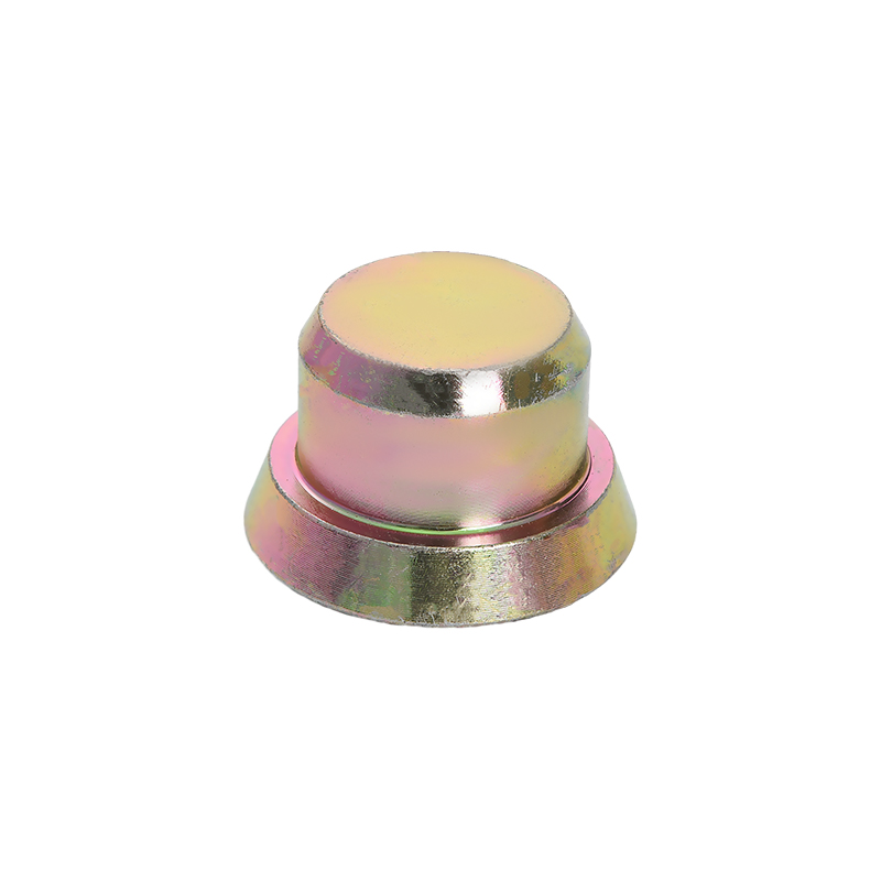
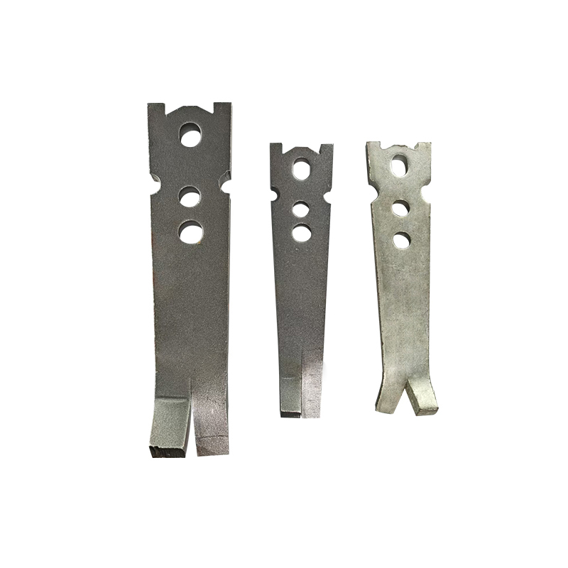 Erection Anchor for Safe Lifting of Precast Concrete ElementsThis anchor is designed to lift and secure precast elements during transport and assembly. Its load capacity depends on concrete strength at stripping, which is critical for safety. Placed accurately, it prevents dangerous swinging during erection.View Product →
Lifting anchors
Lifting anchors are placed at calculated points in the panel based on its weight, geometry, and stripping conditions. A panel that weighs 8 tons might require four anchors with a safe working load of at least 2.5 tons each, depending on the tilt angle during erection. The anchor load capacity depends on concrete strength at stripping, which often reaches 10 to 15 MPa before demolding.
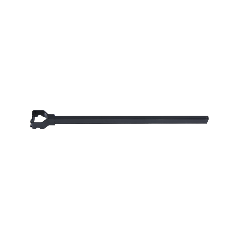
For hollow core or double wall panels, lifting anchors are often cast into specific pockets using an insert magnet. The magnet holds the anchor in position while the concrete cures, then releases with a lever or threaded release mechanism. This is a critical detail because a misplaced anchor can cause a panel to swing sideways when lifted, creating a dangerous situation for the crane operator and crew.
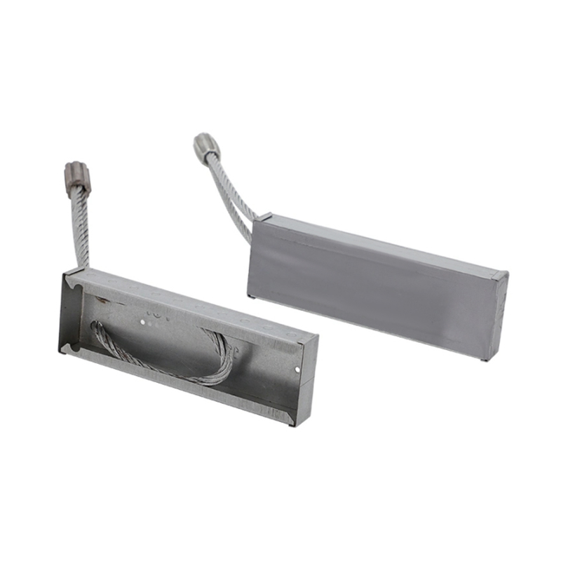
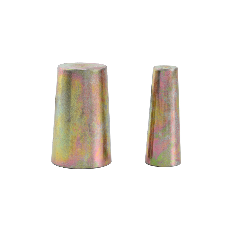 Insert Magnets for Positioning Sockets in Precast FormsInsert magnets hold threaded sockets precisely in formwork during pouring. They ensure correct socket alignment within millimeters, enabling reliable bolt connections. Their magnetic grip releases easily after concrete sets, streamlining production.View Product →
Insert sockets and magnetic positioning
Insert sockets are threaded metal or plastic components that allow post-installation of bolts, lifting clutches, or connection hardware. Their position must be controlled within a few millimeters, because a misaligned socket makes the panel impossible to connect with its neighboring element. Insert magnets hold these sockets in place during the pour. A typical insert magnet sits on the formwork surface, grips the socket with a machined locating pin, and releases after the concrete has set.
A supplier with experience in precast production will offer insert magnets matched to the standard socket dimensions used in the target market. This removes a large portion of trial and error that normally happens on the casting bed. The practical result is that every threaded coupling is exactly where the structural engineer expects it, without the need for repositioning or drilling after stripping.
Connection Details and Edge Profiles
Panel edges are where the details matter most. The shape of the edge determines how two panels meet, whether the joint can seal, and how load transfers between elements. Common edge profiles include:
- Plain square edge for simple interior panels
- Chamfered edge to hide small misalignments and to create a finished joint groove
- Dovetail groove or cast-in corrugated tube for structural connection with cast-in-situ concrete
- Female/male edge profiles for tongue-and-groove joints
Chamfers and their role
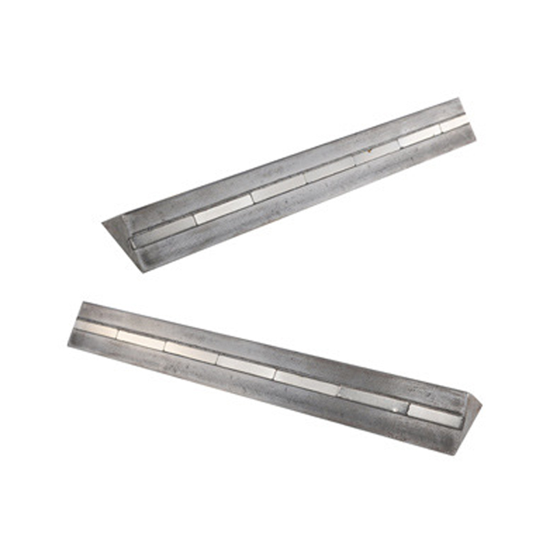
A chamfer is the angled cut at the edge of a panel. It reduces stress concentrations at corners, covers small dimensional deviations, and creates a clean architectural line. Standard chamfer dimensions in precast panels are 10 x 10 mm, 15 x 15 mm, or 20 x 20 mm. The chamfer is produced by a chamfer strip or edge profile fixed to the formwork. When the formwork system uses magnets, a chamfer profile with an integrated magnetic edge touch can be positioned quickly on the shuttering profile. This keeps edge appearance consistent from panel to panel without extra measuring or clamping.
Connection methods between panels
Most precast structures rely on one of three connection classes. The first is a steel connection, where cast-in plates are welded or bolted together. The second is an emulative connection, where rebar is grouted inside corrugated tubes that were cast into the panel. The third is a bearing connection, where the panel edge simply rests on a support. Each method has its own detail requirements for the panel edge. For grouted connections, the corrugated tube position must match exactly with the rebar location on the receiving panel, which is another place where insert magnets earn their keep.
Magnetic Formwork Systems for Panel Production
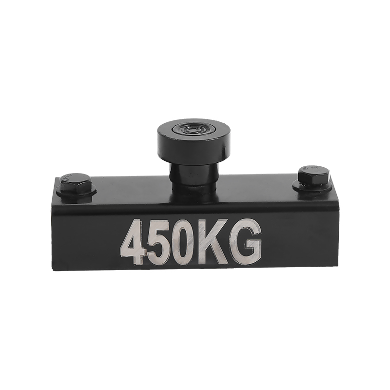
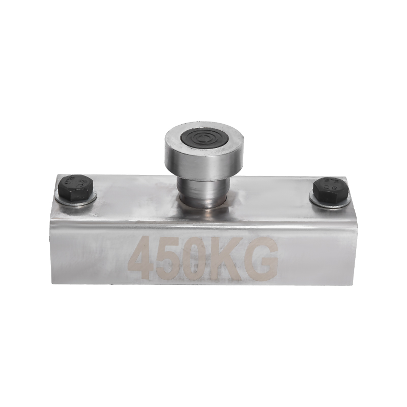
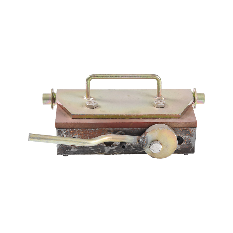
Magnetic shuttering systems use strong neodymium magnets to hold steel formwork against a precast concrete table. The magnet body is switched on and off mechanically. When the lever is in the closed position, the magnet force is active and holds the shuttering profile firmly. When the lever is opened, the magnetic circuit breaks and the magnet disengages.
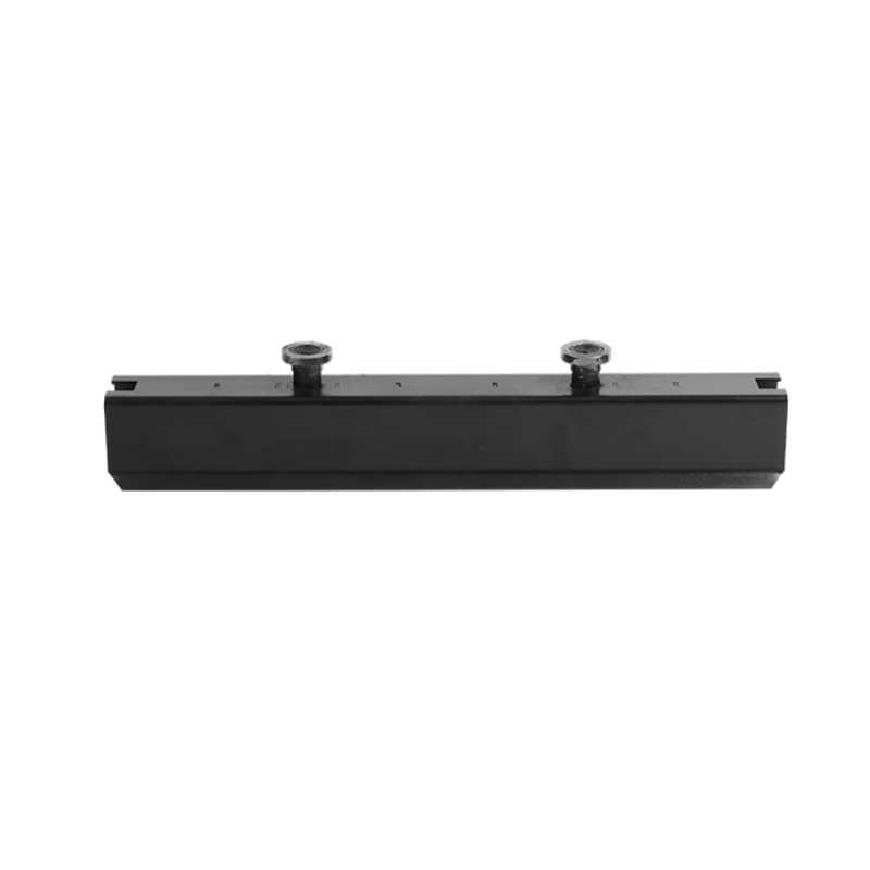
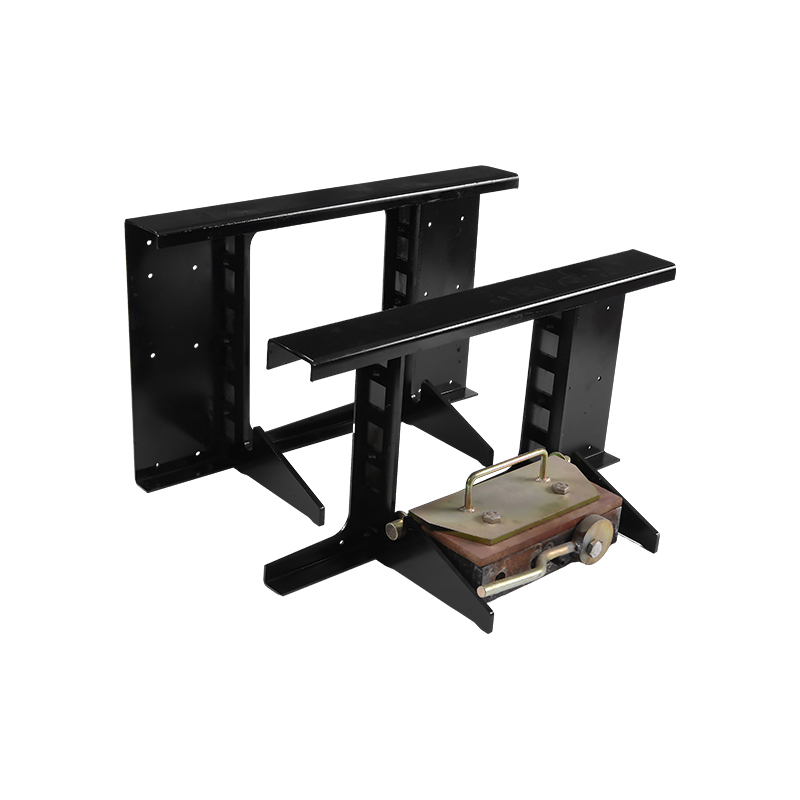 Shuttering Magnet with Handle for Formwork FixationThis magnet holds steel formwork against precast tables, resisting concrete lateral pressure. With a handle for easy switching, it offers holding forces from 450 to 4500 kg. It is reusable and adjustable for various concrete shapes.View Product →
The magnet force is a key specification. A shuttering magnet for precast concrete needs enough lifting force to resist the lateral pressure of fresh concrete and the risk of shifting, but it also needs to release easily. Typical holding forces range from 450 kg to 4500 kg per magnet depending on the application.
| Magnet model | Holding force | Recommended use |
|---|---|---|
| 900 kg | 900 kg | Thin panels, low profile formwork |
| 1200 kg | 1200 kg | Medium wall panels |
| 2100 kg | 2100 kg | Heavy wall panels, close to edge |
| 4500 kg | 4500 kg | Thick panels and long spans |
In practice, the number of magnets placed on one shuttering line is calculated from the concretes lateral pressure at the base of the formwork and the contact area of each magnet. As a general rule, designers specify a safety factor of 2 to 3 times the expected lateral pressure. For a 200 mm thick panel cast vertically, that often translates to one 1200 kg magnet every 400 to 500 mm along the shuttering line.
Magnetic systems reduce setup time because the operator walks along the casting bed, positions the shuttering profile, and toggles the magnet lever. No bolts, clamps, or welding are needed. Shuttering magnets can be reused through hundreds of cycles, which lowers cost per panel compared with reusable timber or steel formwork. The overall casting cycle is also more predictable because formwork drift is virtually eliminated.
Quality Control and Common Issues in Precast Panel Production
Most quality issues in precast panels are traceable to detail mismatches. The most common problems we see in precast plants include:
- Lifting anchor misplaced by 10 mm or more, which causes the panel to tilt during erection
- Insert socket filled with concrete, making connection impossible
- Chamfer missing on the edge, leading to ugly joints or chipped corners
- Rebar displacement resulting in low cover and surface rust marks
- Dimensional deviations of 5 mm or more that prevent panel-to-panel alignment
A practical quality control routine includes:
- Checking embedded part position after magnetic placement with a digital survey device or template
- Verifying magnet holding force at the start of each shift
- Using the same casting table with the same magnetic shuttering setup for identical panel types
- Releasing magnets only after concrete has reached the required minimum stripping strength
- Storing and positioning panels on transport supports that match the lifting points
With a magnetic system, the operator can achieve +/- 1 mm repeatability for shuttering position, assuming the casting table is flat to +/- 1 mm per 3 m and the magnet faces are clean. Dirty magnet faces are one of the main hidden causes of dimensional drift in precast production, so a simple face-cleaning routine at the start of each shift makes a measurable difference in panel tolerance consistency.
Frequently Asked Questions About Precast Panel Details
Whether you are a precast plant manager or a project engineer, these questions come up constantly when the drawings move from design to production.
What is the maximum thickness of a precast wall panel?
Structural precast wall panels typically range from 80 mm to 300 mm in solid form. For double wall panels, two concrete leaves of 40 to 80 mm are connected by a truss, leaving a core space for insulation or structural infill. The practical limit is driven by lifting capacity and transportation dimensions, not by the concrete technology itself.
What tolerance is normal for precast panel dimensions?
With good formwork, a tolerance of +/- 2 mm is realistic for length, width, and thickness. For embedded parts, +/- 2 mm is achievable with magnetic positioning tools. Larger tolerances are allowed by industry guidance, but tighter tolerances improve installation speed and joint quality. The cost of achieving the tighter tolerance is usually much lower than the cost of grouting and shimming on site.
How does a shuttering magnet help with precast panel details?
A shuttering magnet holds the formwork profile in place during the pour. It gives a repeatable edge position, keeps the panel thickness accurate, and allows quick repositioning for different panel geometries. This reduces setup time and minimizes formwork drift. When the magnet is combined with a matched edge profile, the panel edge stays exactly where the drawing says it should.
What is an insert magnet used for?
An insert magnet is used to hold embedded parts (such as threaded inserts, lifting anchors, or chamfer profiles) in position on the casting table before concrete is poured. It keeps the part at the exact designed location for the entire pour cycle. The magnet is switched off after the concrete has gained enough strength, and the part remains firmly embedded in the panel.
How much holding force does a shuttering magnet need?
The required holding force depends on the concrete lateral pressure, which is related to column height and pour rate. A good rule of thumb is to select magnets with a combined holding force of 2 to 3 times the estimated lateral force at the base of the formwork. For a 200 mm panel, this often means a 1200 kg magnet every 400 to 500 mm along the formwork.
Can precast panel details be changed after production?
Only with expensive and risky drilling, which may damage reinforcement. That is why getting details right before pouring is important. Once the panel is cast, moving an embedded part usually requires cutting and grouting, which is often structurally unacceptable. It also voids the architectural finish if the panel has a visible face.
What is the role of a chamfer in precast panels?
The chamfer creates a wedge-shaped edge that disguises small dimensional differences between panels, reduces corner spalling, and forms a clean architectural joint line. It also reduces stress raisers at the panel corner. A 15 x 15 mm chamfer is the most common choice for structural panels, while 10 x 10 mm is used for interior panels where a thinner profile is preferred.
How can I reduce cracking at panel edges?
Keep concrete cover at the designed value, position reinforcement correctly inside the edge zone, and use a chamfer that is large enough to reduce the stress concentration. Also, avoid overvibrating the concrete near the edge. A consistent stripping temperature and a smooth release agent all play a role in preventing edge cracking.
Conclusion
Precast panel details are not just engineering paperwork. They define whether a panel can be lifted, transported, connected, and installed without rework. The shift to magnetic formwork and magnetic insert systems gives producers a practical way to keep very precise control over panel details. Less time is spent on setup, fewer rejection marks occur, and the entire production cycle becomes more predictable.
When you choose a magnetic shuttering supplier, look for strong holding force ratings, a lever mechanism that works reliably over thousands of cycles, and a product line that connects your casting table, your embedded parts, and your lifting system in one coherent system. That is how the best precast plants operate.