English
 Español
 русский
 日本語
日本語
 عربى
عربى
Content
- 1 What Are Precast Concrete Structures and Why They Dominate Modern Construction
- 2 How Precast Concrete Structures Are Manufactured
- 3 Major Types of Precast Concrete Elements and Their Applications
- 4 Precast Concrete Accessories: The Hardware That Makes Structures Possible
- 5 Structural Connections in Precast Concrete Structures
- 6 Schedule Advantages: How Precast Concrete Structures Compress Project Timelines
- 7 Precast Concrete Structures vs. Cast-in-Place: A Direct Comparison
- 8 Prestressed Precast Concrete: How Pre-Tensioning and Post-Tensioning Work
- 9 Seismic Design of Precast Concrete Structures
- 10 Common Mistakes in Precast Concrete Accessory Specification and How to Avoid Them
- 10.1 Specifying accessories without checking concrete cover
- 10.2 Using incompatible hardware from different suppliers
- 10.3 Omitting corrosion protection in the project specification
- 10.4 Failing to coordinate utility sleeves with structural elements
- 10.5 Skipping a dry-run erection check
- 10.6 Not accounting for stripping strength when selecting anchors
- 11 Sustainability in Precast Concrete Structures
- 12 Quality Assurance for Precast Concrete Structures and Accessories
What Are Precast Concrete Structures and Why They Dominate Modern Construction
Precast concrete structures are building components — walls, beams, columns, slabs, and more — manufactured under controlled factory conditions before being transported and assembled on-site. The result is a construction method that consistently outperforms traditional cast-in-place concrete in speed, quality, and cost predictability. Over 60% of large-scale infrastructure projects in Europe and North America now specify precast concrete as the primary structural system, and that figure continues to climb as project timelines shrink and labor costs rise.
The reason precast concrete structures have become the backbone of warehouses, parking garages, bridges, stadiums, and multi-story residential buildings is straightforward: when concrete cures in a factory under precise temperature and humidity controls, its compressive strength routinely reaches 5,000 to 8,000 psi — well above the 3,000 to 4,000 psi typical of field-poured concrete. Every element that holds those components in place, every embed plate, anchor bolt, loop insert, and lifting device, falls under the broad category of precast concrete accessories, and choosing the right accessories is just as critical as the mix design itself.
Key Takeaway: Factory-produced = tighter tolerances, faster schedules, stronger final structure.
How Precast Concrete Structures Are Manufactured
The production of precast concrete structures follows a disciplined sequence that eliminates most of the variables that plague site-poured concrete. Understanding each stage clarifies why the method produces such consistent results and why the selection of precast concrete accessories at the design stage — not during construction — is non-negotiable.
Stage 1 — Form Preparation and Reinforcement Placement
Steel forms, often machined to tolerances of ±1/16 inch, are cleaned, oiled, and assembled. Reinforcing steel cages are prefabricated and set inside. At this stage, all embedded precast concrete accessories — lifting anchors, connection inserts, electrical conduit sleeves, and structural weld plates — are positioned and secured before concrete is poured. Any item that needs to be in the finished element must be placed now; adding it afterward requires coring or cutting, which damages structural integrity.
Stage 2 — Concrete Batching and Placement
Concrete mix designs for precast plants typically use a water-to-cement ratio of 0.35 to 0.45 — considerably lower than field mixes — to achieve high early strength. Internal vibration consolidates the concrete around the rebar cage and embedded accessories. Some plants use external table vibration for thin architectural panels to eliminate surface voids without internal vibrators that might displace thin cover concrete.
Stage 3 — Curing
Precast plants use steam curing, heat curing, or accelerated moisture-retention blankets to reach 70% of design strength within 18 to 24 hours. This rapid strength gain is what allows elements to be stripped from forms and stacked in the yard within a single production shift — a cycle impossible with site-poured concrete that takes 28 days to reach full design strength under ambient conditions.
Stage 4 — Quality Control, Finishing, and Yard Storage
Before any element leaves the casting bed, dimensional checks, surface inspections, and hardware audits confirm that every precast concrete accessory is present, correctly positioned, and undamaged. Elements are then stored on timber dunnage in the yard, organized by delivery sequence, waiting for the transport and erection window.
Major Types of Precast Concrete Elements and Their Applications
Precast concrete structures encompass a wide family of element types, each engineered for a specific structural role. Below is an overview of the most common categories, the buildings and infrastructure they serve, and the typical spans or load ratings involved.
Double-Tee Slabs
Used for parking structures and warehouse floors. Standard spans of 40 to 80 feet with depths of 24 to 34 inches. Load capacity typically 40 to 100 psf superimposed live load.
Hollow-Core Planks
The workhorse of residential and office floor systems. Standard widths of 4 and 8 feet, depths from 6 to 16 inches, spans of 20 to 50 feet. Voids reduce dead load while preserving structural depth.
Precast Columns and Beams
Rectangular and L-shaped columns from 12×12 to 24×24 inches. Inverted-tee beams, rectangular beams, and spandrel beams form the moment frame or simply-supported gravity system.
Precast Wall Panels
Solid, insulated sandwich, and architectural panels from 5 to 12 inches thick. Used as load-bearing shear walls or non-structural cladding. Achieves R-values of 20 to 30 with foam insulation cores.
Bridge Girders
AASHTO I-girders and bulb-tee girders for highway bridges. Spans from 60 to 160 feet. High-performance concrete mixes of 8,000 to 12,000 psi are standard for long-span bridge applications.
Precast Stairs and Landings
Complete stair flights cast as single units with integral landings. Eliminates complex formwork and reduces stair installation from days to hours using just a crane and precast concrete accessories for connection.
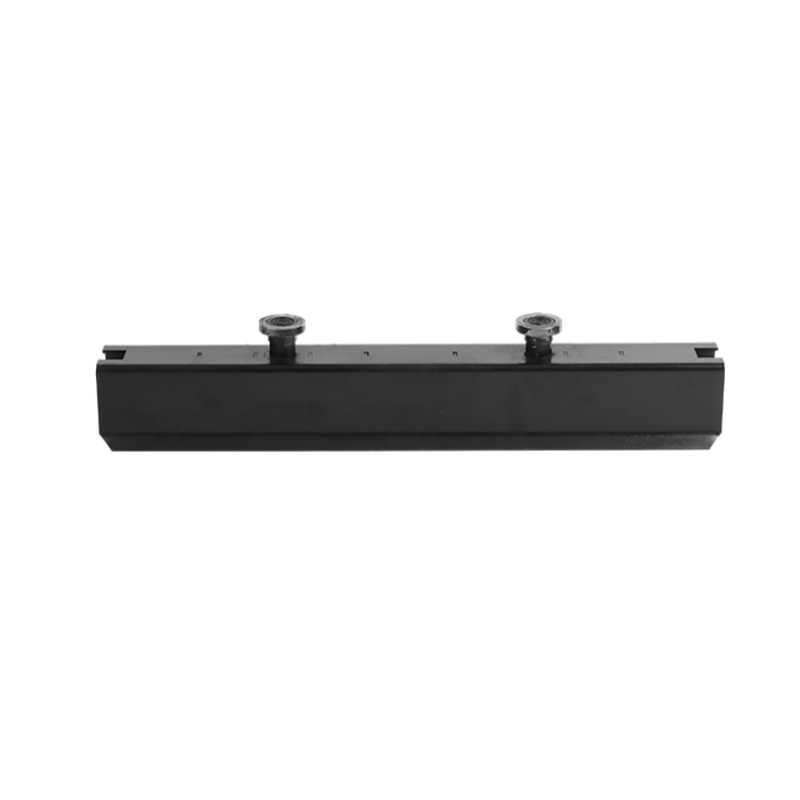
Precast Concrete Accessories: The Hardware That Makes Structures Possible
No matter how precisely a concrete element is designed and cast, it is the precast concrete accessories embedded within it that determine how that element can be lifted, transported, connected, and integrated into a complete structure. Precast concrete accessories span a broad range of hardware types, and each category carries specific load ratings, installation requirements, and compatibility considerations.
| Accessory Category | Function | Typical Working Load | Material |
|---|---|---|---|
| Lifting Anchors (ferrule, loop, coil) | Temporary lifting during stripping and erection | 1 to 60 tons per anchor | Ductile iron, forged steel |
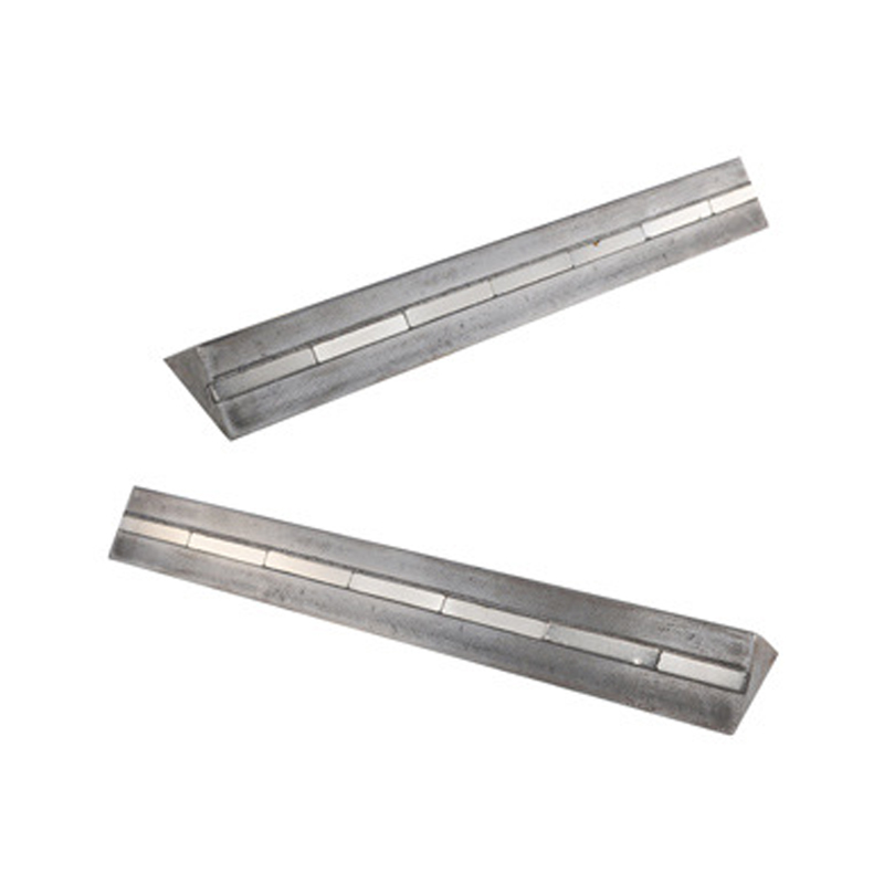
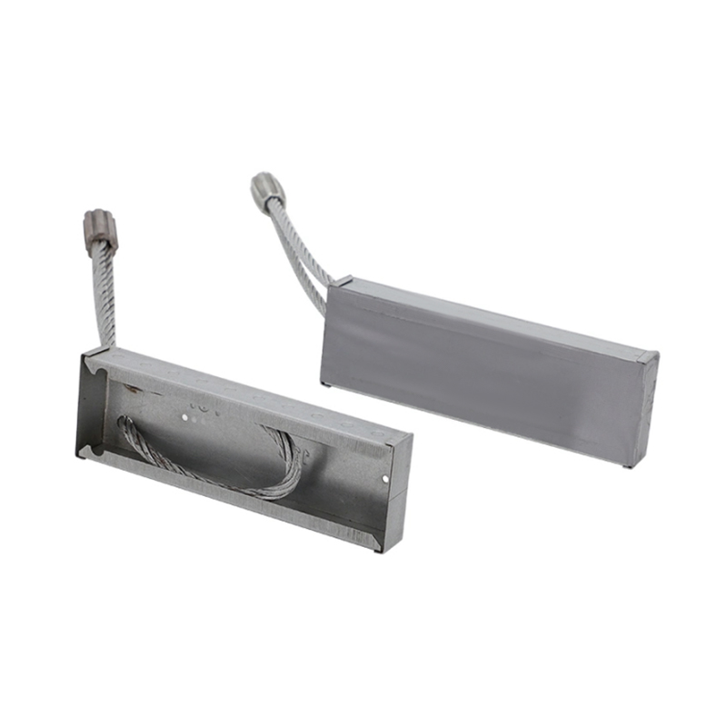
| Embed Plates and Weld Plates | Permanent structural connections between elements | 10 to 200 kips per plate | A36 / A572 steel, hot-dip galvanized or stainless |
| Coil Rods and Coil Bolts | Field-adjustable connections, cladding attachment | 5 to 30 kips per rod | Zinc-plated or stainless steel |
| Bearing Pads | Load transfer and tolerance absorption at bearing seats | Compressive stress 800 to 1,500 psi | Neoprene, HDPE, fiber-reinforced elastomeric |
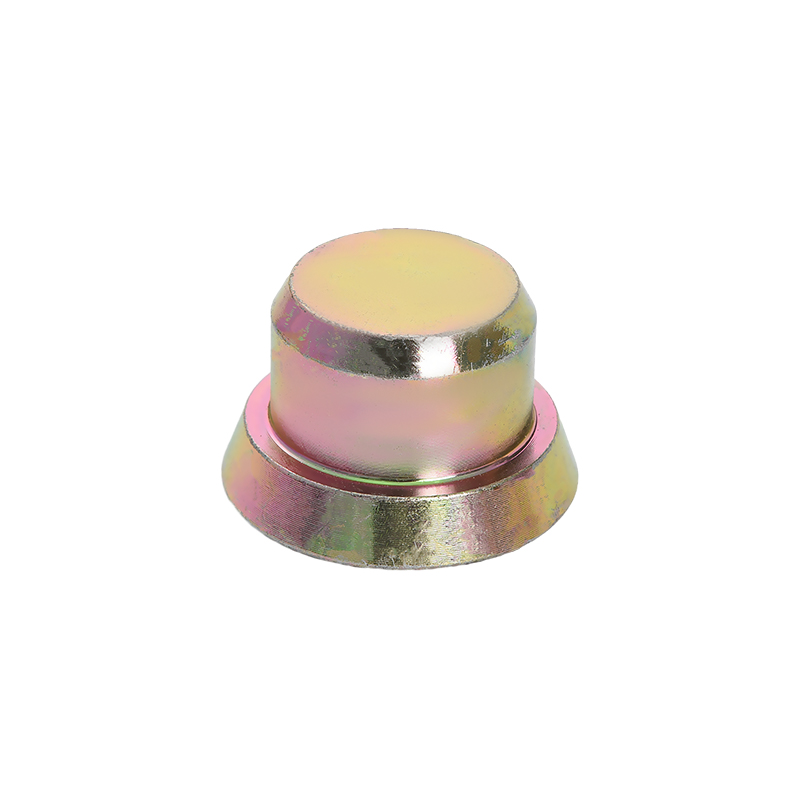
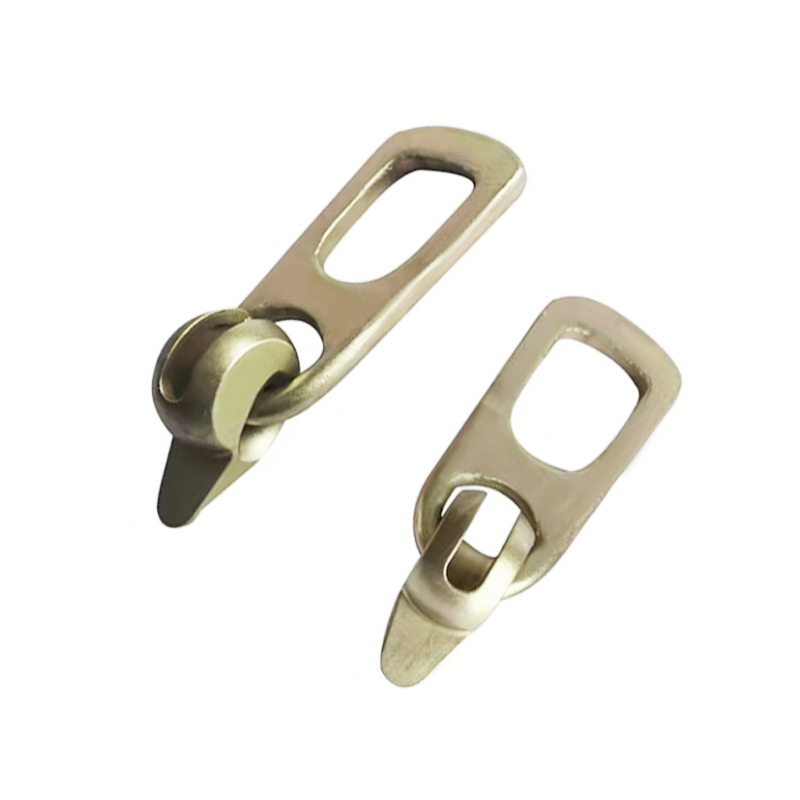
| Loop Inserts and Flared Cone Inserts | Anchor points for secondary attachments, façade hardware | 500 lbs to 5 tons | Malleable iron, steel wire |
| Prestressing Strand and Post-Tension Hardware | Pre-compression of concrete to counteract bending stresses | 270 ksi strand, jacked to 70–75% of UTS | Grade 270 low-relaxation strand |
Lifting Anchors: Sizing and Safety Factors
Lifting anchors are among the most scrutinized of all precast concrete accessories because a failure during stripping or erection is immediately catastrophic. The working load limit (WLL) of any lifting anchor must account for the dynamic impact factor during crane pick — typically a minimum safety factor of 4:1 applied to the concrete breakout and steel tensile failure modes. For a 20-ton precast wall panel, that means the anchor system must be designed for a minimum 80-ton proof load, not just the static panel weight. Rigging angle also reduces capacity: a 60-degree sling angle from vertical reduces the allowable load per leg to approximately 87% of the rated vertical capacity, while a 30-degree angle drops it to 50%.
Embed Plates: Connection Philosophy in Precast Frames
Structural connections between precast concrete elements rely almost entirely on embed plates welded to rebar anchors or nelson studs. The design of these plates follows AISC and PCI guidelines, with particular attention to prying action in tension connections and shear-friction at interface planes. A properly designed weld plate connection in a precast parking structure can transfer 150 kips of shear across a beam-column joint with a plate as small as 8×8 inches — provided the shim stack, grout pocket, and field weld are executed to specification. Galvanizing these plates to ASTM A123 (minimum 3.9 oz/ft²) adds measurable corrosion life in exposed or marine environments.
Bearing Pads: Tolerances and Long-Term Performance
Every precast beam, double-tee, and hollow-core plank rests on a bearing pad that simultaneously transfers vertical load and accommodates the thermal and shrinkage movements that occur over the life of the structure. Neoprene pads of 50 to 60 durometer hardness are the most common choice, with standard dimensions of 4×6 inches to 8×12 inches and thicknesses of 3/8 to 3/4 inch. PCI Design Handbook tables show that a 6×9 inch, 1/2-inch neoprene pad can accommodate up to 0.5 inch of horizontal movement while maintaining adequate compressive stiffness. HDPE pads are increasingly specified for bridge applications where low friction is needed to allow thermal expansion without restraint forces building up in the superstructure.
Structural Connections in Precast Concrete Structures
The connection system is where precast concrete structures either perform or fail. Unlike steel frames, where connections are made with bolts and welds in open air, precast concrete connections often involve confined spaces, grout pockets, and embedded hardware that cannot be inspected after grouting. Getting the connection right the first time is therefore non-negotiable.
Three broad philosophies govern precast connection design:
- Simply-supported gravity systems — beams rest on corbels or ledger angles, transferring only vertical load. Simple, fast to erect, and tolerant of differential settlement. Used in the vast majority of single-story industrial buildings and parking structures.
- Moment-resistant frames — column-to-column and beam-to-column connections are made moment-resistant through post-tensioning, grouted rebar couplers, or welded plate assemblies. Achieves lateral drift control comparable to cast-in-place frames for seismic and wind resistance.
- Hybrid systems — gravity loads carried by simple bearing, lateral loads handled by a separate shear wall or moment frame core. The most common approach for mid-rise residential and mixed-use precast buildings of 5 to 15 stories.
The quality of grouted connections in particular depends heavily on the selection and placement of precast concrete accessories. A grouted sleeve coupler — used to splice two rebar lengths across a joint — must be aligned to within ±1/8 inch for the bar to enter cleanly during erection. Any misalignment discovered on-site typically requires expensive remediation involving mechanical anchors or epoxy injection, both of which reduce the connection's ductility compared to the original design intent.
±1/8" Max coupler misalignment tolerance
4:1 Minimum lifting anchor safety factor
28 days Site pour cure vs. 18–24 hrs precast
8,000 psi Typical precast HPC compressive strength
Schedule Advantages: How Precast Concrete Structures Compress Project Timelines
The single most compelling argument for precast concrete structures on commercial and infrastructure projects is schedule compression. Fabrication of elements happens in parallel with site preparation — while the foundation is being excavated and poured, the precast plant is simultaneously producing the structural frame. This overlap typically saves 4 to 8 weeks on a mid-size project compared to a sequential cast-in-place schedule.
Weeks 1–4: Design and Shop Drawing Approval
Engineer of record and precast engineer of record collaborate on connection details, embed locations, and precast concrete accessories schedules. Every accessory is drawn, dimensioned, and specified in the shop drawings before a single form is assembled.
Weeks 5–12: Plant Production
Full production runs. A medium-size precast plant casting 500 to 800 cubic yards per week can produce the structural frame for a 200,000 square foot warehouse in 6 to 8 weeks. Elements are serial-numbered and sequenced for delivery.
Weeks 8–14: Site Foundations (Parallel)
While plant production runs, the site crew pours footings, grade beams, and column piers. Anchor bolt templates derived from the precast shop drawings ensure that column base plates and spigot connections will align when elements arrive.
Weeks 13–18: Erection
A well-organized erection crew with one 150-ton crawler crane can set 20 to 40 major elements per day. A five-story parking structure of 1,200 spaces can be structurally complete in 10 to 14 working days of crane time — a speed impossible to approach with cast-in-place methods.
Weeks 18–22: Grouting, Welding, and Finishing
Field crews complete grouted connections, field welds at embed plates, joint sealants, and any architectural finishing. The structure is fully enclosed and weather-tight far earlier than equivalent cast-in-place construction.
Precast Concrete Structures vs. Cast-in-Place: A Direct Comparison
The choice between precast and cast-in-place concrete is never simple, but the following comparison covers the dimensions most important to owners, contractors, and structural engineers making that decision.
| Dimension | Precast Concrete | Cast-in-Place Concrete |
|---|---|---|
| Compressive Strength | 5,000–12,000 psi typical | 3,000–5,000 psi typical |
| Dimensional Tolerance | ±1/8 to ±1/4 inch | ±1/4 to ±3/4 inch |
| Schedule (structural frame, 200k sf warehouse) | 10–14 days erection | 8–14 weeks forming/pouring |
| Weather Dependency | Low — curing done in plant | High — cold and hot weather require protection |
| Design Flexibility | Repetitive geometry optimal; custom shapes possible at premium | High flexibility for complex, curved, or irregular geometry |
| Site Labor | Low — primarily crane and connection crews | High — forming, placing, finishing, stripping |
| Quality Control | PCI plant certification, daily QC testing | Dependent on field conditions and inspector presence |
Prestressed Precast Concrete: How Pre-Tensioning and Post-Tensioning Work
The combination of prestressing and precast concrete is one of the most powerful tools in structural engineering. By pre-compressing the concrete before service loads are applied, engineers can effectively eliminate tensile cracking — the primary mode of concrete deterioration — and achieve spans that would be structurally impossible or economically impractical with conventionally reinforced sections.
Pre-Tensioning: The Standard Precast Approach
In pre-tensioned precast concrete, high-strength steel strands are stretched between abutments at the ends of the casting bed before concrete is placed. The strands — typically Grade 270 low-relaxation, 0.5 or 0.6 inch diameter — are jacked to approximately 70% of ultimate tensile strength, or roughly 189,000 psi. Concrete is then placed around the tensioned strands. When the concrete reaches adequate strength, the strands are released and the pre-compression transfers into the element by bond. This is the method used to manufacture hollow-core planks, double-tees, bridge girders, and prestressed wall panels in virtually every precast plant in the world.
Post-Tensioning in Precast Elements
Post-tensioning hardware — ducts, anchors, couplers, and trumpet plates — represents a specialized category of precast concrete accessories used when prestress must be applied after the element has been erected or when elements from multiple precast segments must be joined into a continuous structural unit. Segmental bridge construction, for example, uses precast segments typically 8 to 12 feet long that are assembled and then post-tensioned into continuous girders of 200 to 400 feet. Each post-tensioning tendon may carry 300 to 1,500 kips of prestressing force depending on strand count and geometry.
Long-Term Prestress Losses
Engineers must account for prestress losses when sizing strands and specifying the initial jacking load. The main sources of loss over the service life of a prestressed element are:
- Elastic shortening — immediate loss at strand release, typically 6 to 8% of initial prestress for pre-tensioned elements
- Creep — time-dependent deformation under sustained load, accounting for 5 to 12% of effective prestress over a 50-year life
- Shrinkage — volumetric reduction as concrete dries, contributing 4 to 8% additional loss
- Steel relaxation — gradual loss of strand stress at constant strain, approximately 2% for low-relaxation strand over 50 years
Total long-term losses typically range from 15 to 25% of the initial jacking force. This means a strand jacked to 33,000 lbs must be designed to carry effective prestress of 25,000 to 28,000 lbs throughout the design life — and the section design must account for the reduced pre-compression when calculating cracking moments and deflections.
Seismic Design of Precast Concrete Structures
The behavior of precast concrete structures under seismic loading has been studied intensively since the 1971 San Fernando earthquake and 1994 Northridge earthquake revealed weaknesses in early precast parking structures. The engineering community responded with major advances in connection design, diaphragm detailing, and seismic testing programs — most notably the PRESSS (PREcast Seismic Structural Systems) research program that ran from 1991 to 2001.
The PRESSS program demonstrated that properly detailed precast systems can match or exceed the ductility of cast-in-place concrete frames. The jointed wall system developed in PRESSS used unbonded post-tensioning through precast shear wall panels to provide self-centering behavior — the building rocks at the wall-to-foundation interface under seismic loading but returns to plumb when the earthquake stops, with minimal residual drift. A full five-story precast structure was tested at 60% of full scale at the UC San Diego Structural Laboratory and demonstrated residual drifts of less than 0.1% after testing at design-level earthquake motions.
Current ASCE 7 and ACI 318 provisions allow precast concrete structures in Seismic Design Category D (high seismic) provided that connections and diaphragms are detailed to comply with the ductile precast special moment frame or precast special shear wall systems. Key requirements include:
- Grouted sleeve connections must demonstrate 125% of bar yield strength in tensile tests prior to use in construction
- Precast diaphragm connections must be designed using the Diaphragm Seismic Design Method (DSDM) with force amplification factors of 1.0 to 1.5 depending on diaphragm classification
- Chord and collector connections along diaphragm edges carry amplified diaphragm forces that frequently govern the sizing of precast concrete accessories at panel-to-panel joints
- All precast concrete accessories in the seismic force-resisting system must be designed for the expected material strengths and the overstrength factor omega-zero specified in ASCE 7 Table 12.2-1
Common Mistakes in Precast Concrete Accessory Specification and How to Avoid Them
Experienced precast engineers and contractors consistently identify the same categories of errors on projects that result in field problems, remediation costs, or schedule delays. Most of them trace back to accessory specification and coordination decisions made during design — long before concrete is ever poured.
01
Specifying accessories without checking concrete cover
A common error is specifying a lifting anchor that, at its required embedment depth, conflicts with the reinforcing cage or post-tensioning duct. Minimum concrete cover over any precast concrete accessory must be maintained at the specified minimum — typically 1 inch for formed surfaces in interior exposure and up to 2 inches in corrosive or marine environments. Verify accessory dimensions against the rebar layout in 3D BIM before issuing shop drawings for approval.
02
Using incompatible hardware from different suppliers
Lifting systems — anchor plus lifting clutch — are designed as matched pairs. Using a clutch from Supplier A with an anchor from Supplier B voids the load rating of both components. Every precast concrete accessories specification should require that lifting systems be matched sets from a single manufacturer, with load testing documentation supplied for the project record.
03
Omitting corrosion protection in the project specification
Embed plates and weld plates specified as plain A36 steel will corrode rapidly in any exposed or exterior application. Hot-dip galvanizing to ASTM A123 adds 30 to 50 years of corrosion life in typical outdoor exposure. In marine splash zones, specify Type 316 stainless steel or epoxy-coated hardware with a documented quality assurance process for coating continuity.
04
Failing to coordinate utility sleeves with structural elements
Electrical conduit, plumbing sleeves, and mechanical penetrations embedded as precast concrete accessories must be coordinated with the structural engineer before shop drawing approval. A 6-inch opening through the web of a prestressed double-tee must be analyzed for shear reduction; an uncoordinated penetration discovered after elements are cast typically requires expensive external reinforcement straps or element replacement.
05
Skipping a dry-run erection check
On complex precast structures — particularly those with moment connections requiring field-welded embed plates — a dry-run review of the accessory layout against the structural model catches alignment conflicts before erection begins. Discovering a 1-inch misalignment between two weld plates on the ground costs minutes; discovering it 50 feet in the air costs days and significant rework expense.
06
Not accounting for stripping strength when selecting anchors
Lifting anchors must be evaluated against the concrete strength at the time of stripping — not the 28-day design strength. If an element is stripped at 16 hours, concrete strength may be only 2,500 to 3,000 psi. Anchor capacity tables must be entered at the actual stripping strength, and the concrete breakout capacity reduced accordingly. Many lifting anchor failures occur precisely because the specified anchor capacity was calculated at 5,000 psi while the element was stripped at 18 hours with concrete at only 2,200 psi.
Sustainability in Precast Concrete Structures
The sustainability profile of precast concrete structures has improved substantially over the past two decades, driven by both regulatory pressure and genuine innovation in materials and production methods.
Supplementary Cementitious Materials (SCMs)
Fly ash, slag cement, and silica fume — collectively called supplementary cementitious materials — can replace 20 to 50% of portland cement in precast concrete mixes without compromising strength or durability. Since cement production accounts for approximately 8% of global CO₂ emissions, a precast mix with 35% slag replacement reduces the embodied carbon of the concrete by approximately 25 to 30% compared to a 100% portland cement baseline, while also improving long-term durability through reduced permeability.
Reduced Material Waste
Factory production of precast elements generates concrete waste rates of less than 2% of total batch volume, compared to 8 to 12% waste on typical site-poured projects where over-ordering and spillage are common. Steel form reuse — a single precast form can produce 300 to 1,000 identical elements over its service life — eliminates the lumber waste associated with cast-in-place forming systems.
Thermal Mass and Energy Performance
Precast concrete wall panels, particularly insulated sandwich panels, provide substantial thermal mass that smooths diurnal temperature swings in building interiors. A 6-inch insulated precast sandwich panel with a continuous 2-inch EPS core achieves approximately R-13 at center of panel — competitive with a steel stud wall assembly — while also providing the structural and fire resistance functions that a stud wall cannot match without additional systems.
End-of-Life Considerations
Precast concrete elements can be deconstructed rather than demolished when structures are eventually dismantled, because the discrete bolted and welded connections used in precast frames — including all the precast concrete accessories that form those connections — can be unbolted or flame-cut. Recovered precast elements have been reused in secondary structures such as retaining walls, sound barriers, and temporary construction facilities. When crushing is unavoidable, recycled concrete aggregate from precast demolition is clean, consistently graded, and suitable for road base, drainage aggregate, and structural fill.
Quality Assurance for Precast Concrete Structures and Accessories
The quality control environment in a PCI-certified precast plant is substantially more rigorous than what is achievable on most construction sites. Understanding what happens during plant QC helps owners, engineers, and contractors set appropriate expectations for what the plant can and cannot guarantee — and where field quality control must pick up the slack.
In-Plant QC: What Gets Checked at Every Stage
- Incoming materials — Cement, aggregates, admixtures, and precast concrete accessories all require incoming inspection and mill certification review. Lifting anchors from every batch are typically proof-tested at 150% of rated working load before acceptance.
- Form setup — Dimensional verification of form geometry and accessory placement before concrete is batched. Deviations greater than the PCI tolerance table values for that element type require correction before pouring proceeds.
- Fresh concrete — Slump, air content, unit weight, and temperature are tested at point of discharge for every concrete batch. Cylinder samples are cast for 1-day, 7-day, and 28-day compressive strength testing.
- Finished elements — All precast concrete accessories are located and measured after stripping. Surface finish defects are documented, repaired per an approved repair procedure, and re-inspected before the element is released to the yard.
Third-Party Inspection During Erection
Field inspection of precast erection focuses on four primary items: bearing seat preparation and bearing pad placement, grout and non-shrink grout application in connection pockets, field welds at embed plate connections, and joint sealant installation. Field weld inspection requires a CWI (Certified Welding Inspector) and visual inspection plus ultrasonic testing for full-penetration welds in the primary structural connections. Bearing pad placement is frequently under-inspected and under-specified on low-bid projects; a misaligned or missing bearing pad can cause local crushing of the concrete ledge within days of load application.