English
 Español
 русский
 日本語
日本語
 عربى
عربى

Content
- 1 What Precast Concrete Wall Details Include
- 2 Key Wall Panel Types and Their Detail Requirements
- 3 Reinforcement and Embedment Details
- 4 Connection and Lifting Details
- 5 Joint Details and Surface Sealing
- 6 Formwork and Manufacturing Methods for Wall Panels
- 7 Quality Control and Common Issues in Wall Details
- 8 Installation and Field Considerations for Wall Panels
- 9 Frequently Asked Questions About Precast Concrete Wall Details
- 10 Final Recommendations for Precast Wall Details
The four most critical precast concrete wall details are the reinforcement layout, embedded connection hardware, joint sealing system, and panel lifting points. These elements determine whether a wall panel performs structurally, resists moisture penetration, and installs efficiently on site. When any of these details is under-specified, panels can develop hairline cracks, leak through joints, or stall erection. During our years of working with precast factories, we have seen teams that define these details at the design stage reduce rework by 15% to 30% compared with crews that address them only after casting.
What Precast Concrete Wall Details Include
Precast concrete wall details are the complete set of engineering specifications that define how a prefabricated concrete wall is built, connected, sealed, and installed. They cover reinforcement steel positions and sizes, embedded plates, lifting hardware, edge chamfers, joint profiles, anchor systems for erection, and sealant configurations.
Standard precast wall panels typically use thicknesses between 120 mm and 300 mm, widths from 2.4 m to 3.6 m, and heights that can extend beyond 12 m in tall structures. Wall details are documented in shop drawings that follow recognized industry standards such as PCI (Precast/Prestressed Concrete Institute) and EN 13225. These documents specify dimensional tolerances of ±2 mm for joint alignment and ±5 mm for overall panel dimensions.
A complete detail package also includes the concrete mix design, cover depths for reinforcement, and the type of connection hardware. The cover depth for exterior wall panels is commonly set at 30 mm to 50 mm to achieve the required fire resistance rating, typically a 2-hour rating for standard wall sections. Every element of the detail package has one purpose - to ensure the wall behavior under service loads is predictable and repeatable.
Key Wall Panel Types and Their Detail Requirements
The choice of wall panel type determines the details you need. Each panel type has a different structural role, and the details must be adjusted accordingly.
| Panel Type | Typical Thickness | Core Function | Common Application |
|---|---|---|---|
| Solid | 120–200 mm | Structural + exterior facade | Industrial, retail and warehouse buildings |
| Insulated Sandwich | 200–350 mm | Structural + thermal insulation | Residential and office buildings |
| Ribbed | 150–250 mm | Structural + high load reinforcement | High wind and seismic regions |
| GFRC (Glass Fiber Reinforced) | 15–30 mm | Architectural facade only | Decorative building fronts, stadium exteriors |
Solid panels demand the most attention to connection and lifting details because the full thickness is structural. Insulated sandwich panels add a thermal break layer between two concrete wythes, with connectors called wythe ties placed every 300 mm to 600 mm in both directions. Ribbed panels need careful formwork details for the rib geometry, while GFRC panels rely on a lightweight edge framing system and stainless steel anchors for attachment to the structural frame.
Reinforcement and Embedment Details
The reinforcement cage inside a precast wall is detailed to resist bending from wind loads, self-weight, and accidental impact. Typical rebar sizes are 12 mm to 20 mm diameter, spaced at 150 mm to 200 mm centers. The splice lengths for rebar in precast panels are often increased to 50d to 60d (50 to 60 times rebar diameter) to ensure continuity at construction joints.
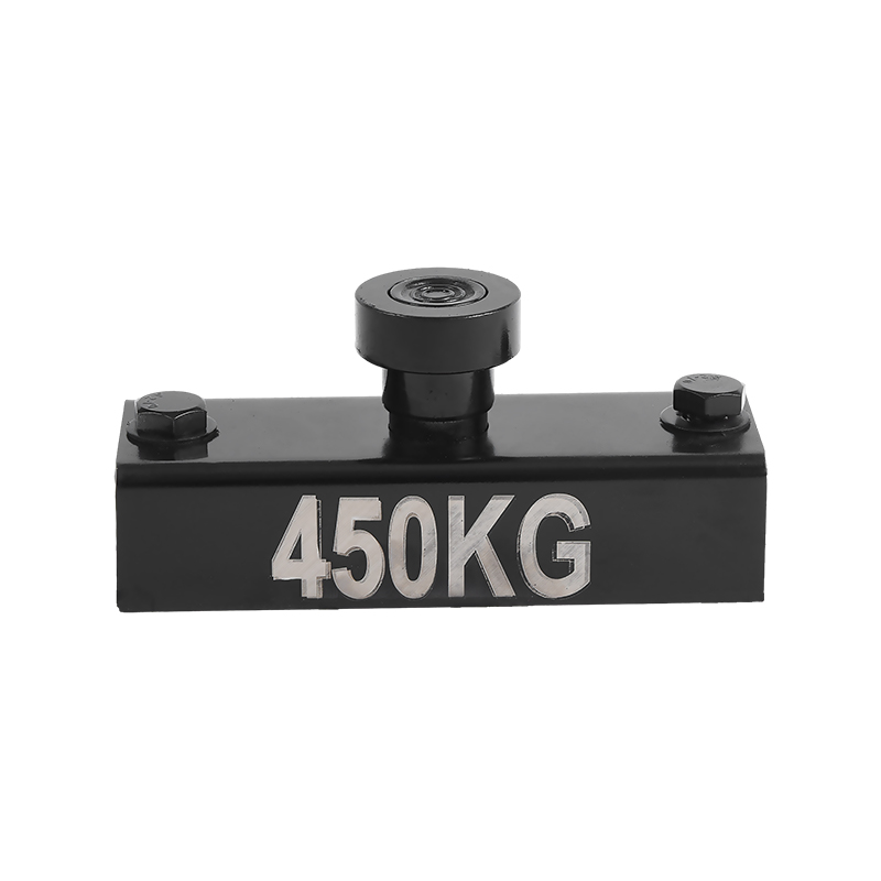
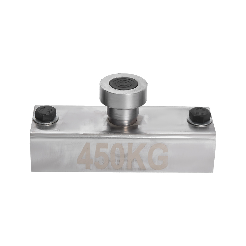
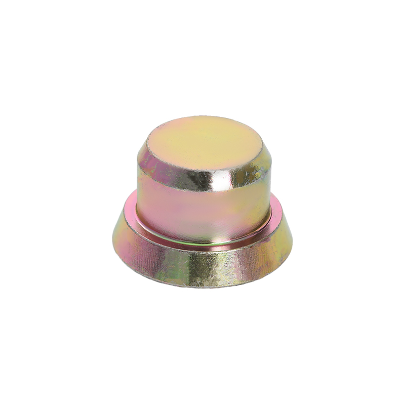
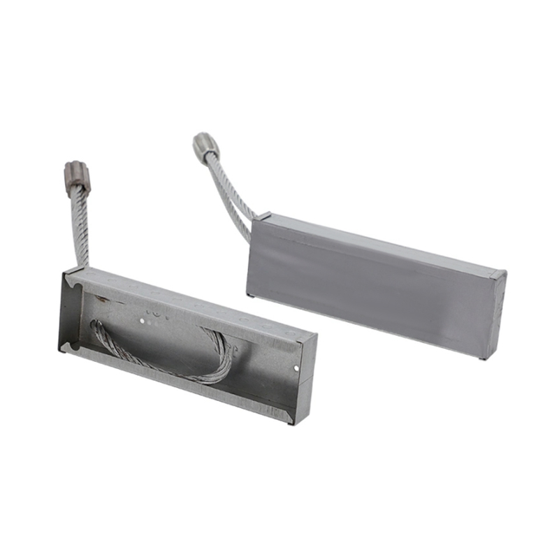
Embedments are cast into the concrete for lifting, connecting, and aligning. The most common embedment types are lifting inserts, threaded connection inserts, and ferrule-type sockets. Insert magnets are widely used in precast production to lock these embedments precisely into the formwork before casting. They hold the inserts within ±1 mm of the desired position, which is far tighter than wooden or manual methods can achieve consistently.
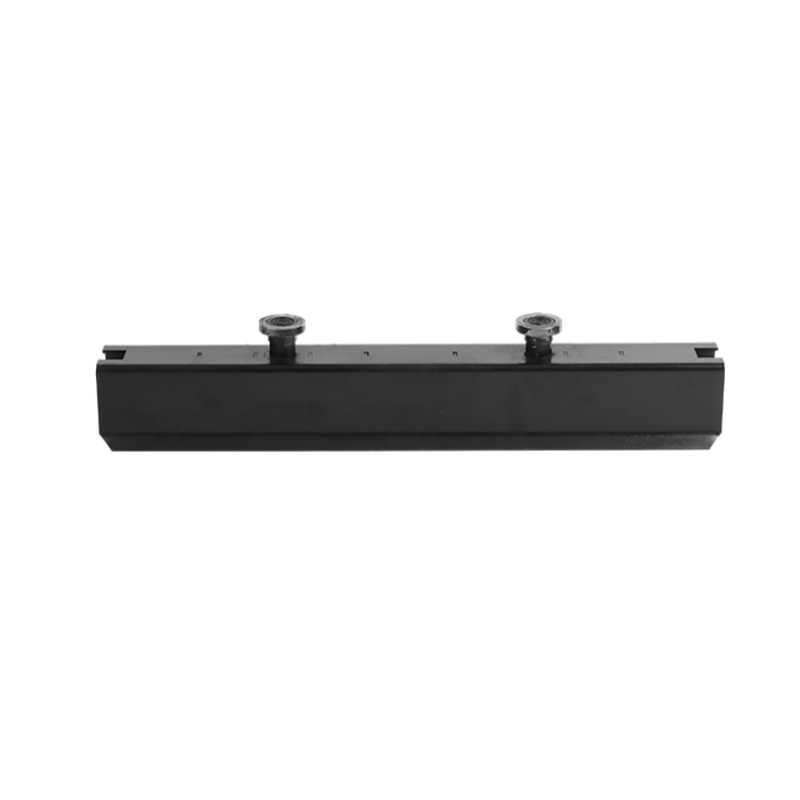
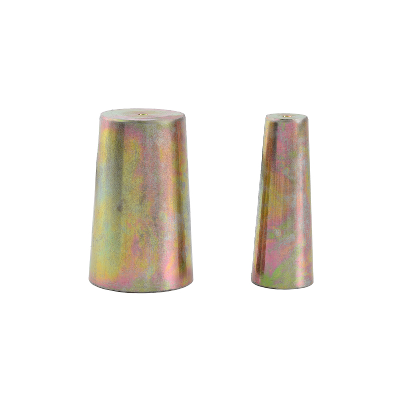 Precast Insert Magnets for Accurate Embedment PositioningInsert magnets secure embedments within ±1 mm, far exceeding manual methods. They reduce positioning time from minutes to seconds, eliminating errors and speeding up precast panel production.View Product →
Insert magnets also cut the labor needed for positioning from several minutes per embedment to seconds. A precast wall panel requires anywhere from 6 to 12 embedments depending on size and connection strategy. With a manual positioning approach, placement and checking adds roughly 20 to 30 minutes per panel. Using a magnetic insert magnet reduces this to 5 minutes or less, while also eliminating a major source of position errors.
The role of insert magnets in precast concrete production is covered in more detail in our technical article on insert magnets, which explains the positioning sequence and verification methods used in real production lines.
Connection and Lifting Details
Lifting and connection details are where precast wall panels either succeed or fail. A standard concrete wall panel with a height of 3 m and thickness of 180 mm weighs approximately 1.3 to 1.5 metric tons per meter of width. A 3.6 m x 12 m wall panel can weigh more than 18 tons, which means lifting hardware must be rated at 1.5 times the panel weight by safety regulations.
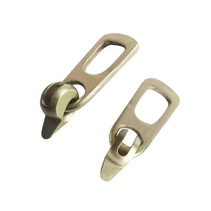
Erection anchors are the most widely used lifting points for precast wall panels. They are embedded near the top of the panel and engage with a clutch that allows the crane to lift the panel in a nearly vertical orientation. Different anchor styles support various lifting methods:
- Two-hole anchors provide a simpler lifting connection and are favored for smaller panels.
- Lifting clutches are used together with erection anchors to allow quick release after the panel is set.
- Threaded inserts allow bolted connections for permanent structural attachment.
When designing the connection detail, the engineer must specify both the ultimate and serviceability load paths. The panel-to-frame connection should handle wind suction, shear from thermal movement, and gravity. A common detail is a slotted bracket that permits approximately 10 mm to 15 mm of horizontal adjustment on site. This tolerance reduces the alignment difficulty without compromising the structural joint.
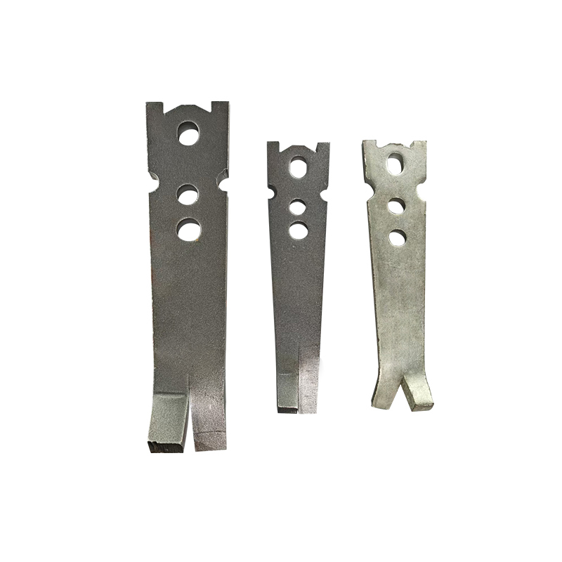 Durable Erection Anchors for Precast Lifting and AlignmentErection anchors handle high loads and resist corrosion. They facilitate precise lifting and alignment of precast elements, supporting safe installation and reducing site adjustment needs.View Product →
Joint Details and Surface Sealing
Joint design is the most common source of site complaints in precast wall construction. The joints between panels must accommodate thermal expansion and shrinkage while keeping water out. Vertical joints in precast wall panels are typically 10 mm to 20 mm wide, while horizontal joints are set wider at 15 mm to 25 mm to account for tolerance accumulation across a floor line.
A properly detailed joint uses a two-stage sealing system. The first stage is a backer rod and one or two beads of a low-modulus elastomeric sealant, typically silicone, polyurethane, or polysulfide. The second stage is a continuous gasket or compression seal that provides a secondary barrier if the sealant fails. Sealant depth should be at least 6 mm, and the joint durability increases dramatically when the sealant is applied over primed concrete with a tooled concave profile.
Edge preparation for later sealing
The edge of a precast wall panel has a chamfered profile to guide the sealant and reduce stress at the interface. A precast concrete chamfer is a wedge-shaped profile, commonly 20 mm x 20 mm, cast directly onto the panel edge during production. Without a chamfer, the sealant can tear at the sharp concrete edge, reducing joint life. Our article on how precast concrete chamfer improves surface quality explains the production methods and the impact on finished panel appearance.
Water penetration tests on precast wall assemblies consistently show that panels with a two-stage joint system and correctly detailed chamfers pass at 75 kPa water pressure without leakage, while single-stage systems fail around 30 to 40 kPa.
Formwork and Manufacturing Methods for Wall Panels
Precast wall panels are manufactured in either horizontal table forms or vertical battery molds. Horizontal forms give easier access to the top surface for embedment placement and finishing, while battery molds are used for long runs of identical panels to improve production cycle time.
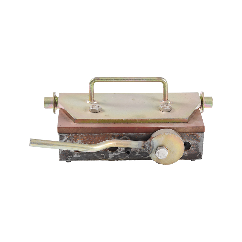
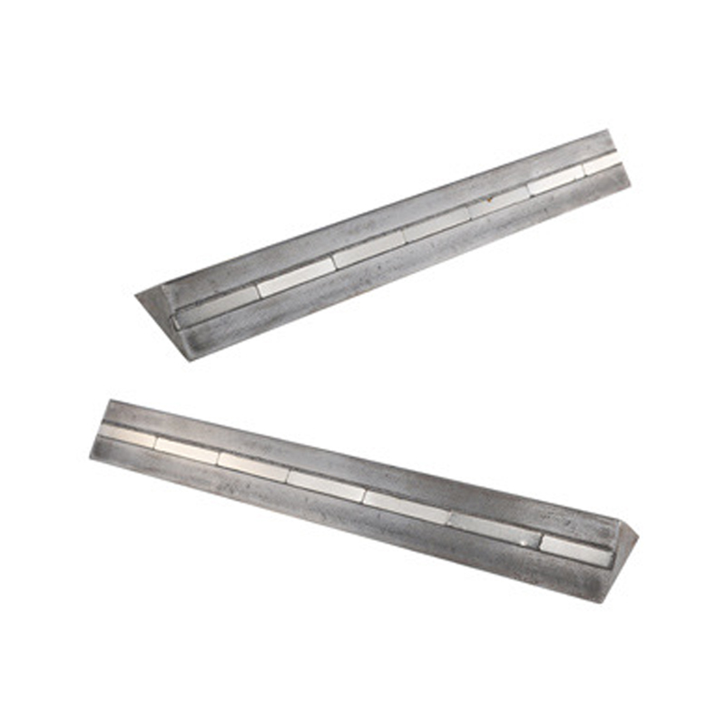
Magnetic formwork systems have largely replaced wooden and steel bolted forms in modern precast plants. A shuttering magnet with handle grips the steel formwork table and holds the form profile under the vibration forces of concrete casting. A standard shuttering magnet generates a holding force of 900 kgf to 2,500 kgf, which is more than sufficient to keep the form edge from creeping during vibration.
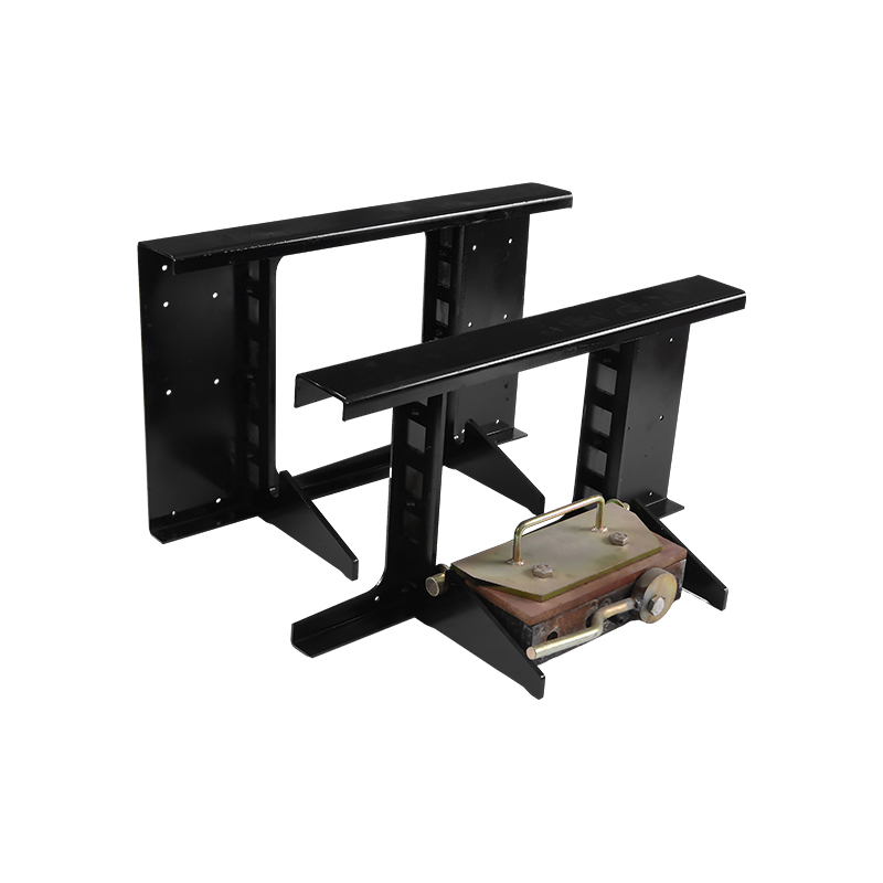 Handled Shuttering Magnets for Precast Formwork StabilityShuttering magnets with handles generate 900–2500 kgf holding force, keeping formwork rigid during vibration. They streamline reusable formwork setup, improving precast plant efficiency.View Product →
The advantages of magnetic shuttering in precast wall detail work include:
- Repositioning time drops from 10 minutes to under 1 minute per line.
- The magnet holds its position through multiple pours, reducing setup variability.
- The cast edge quality is better, because the form no longer shifts under vibration.
- There is no risk of formwork breakage on complex wall details, as the magnets release without impact.
In wall panel production, the formwork must hold the edge chamfers that create the joint profiles discussed earlier. Given the dimensional tolerance of ±2 mm, magnetic holding is the most reliable way to maintain that precision across hundreds of casting cycles.
Quality Control and Common Issues in Wall Details
The biggest quality challenges in precast wall production are dimensional accuracy, edge spalling, and surface blemishes. The table below summarizes the most common issues and the detail changes that resolve them.
| Defect | Acceptable Tolerance | Detail Fix | Impact on Site Work |
|---|---|---|---|
| Edge spalling | ≤5 mm deep | Use chamfered form edges with clean stripping | Reduces patching and improves sealant adhesion |
| Bow (out-of-plane) | ≤L/240 | Increase stripping age and improve curing | Less shimming on site |
| Joint misalignment | ±2 mm | Use insert magnets and magnetic formwork for embedment accuracy | Eliminates costly joint trimming |
| Honeycombing | No exposed aggregate voids | Adjust mix design and vibration time | No structural repairs required |
A consistent QC check at the formwork stage catches most of these issues before they become concrete. Measuring panel flatness with a straightedge and checking embedment positions against shop drawings with a tape measure is the minimum needed. Our experience from precast plants shows that using magnetic positioning for embedments and formwork reduces edge spalling incidence by over 40% compared to manual placement.
Installation and Field Considerations for Wall Panels
For a precast wall panel, the erection sequence and temporary bracing are just as important as the permanent structure. The lifting algorithm must account for the panel's center of gravity, which is not at the geometric center for panels with window openings or equipment embedments. A lifting beam or spreader bar is required when panels exceed 3 m in width to keep the lifting points vertical.
Temporary bracing must remain in place until the permanent connections are established. The bracing is typically rated for 25% of the wind load on the panel, and bolt or clamp connections should be checked for overturning stability. The typical bracing arrangement uses two braces at a 45-degree angle, anchored to floor inserts rated at 20 kN each.
To ensure a smooth installation flow, the site manager should verify the following on the wall detail drawings:
- Lifting point location and load rating match the crane and rigging available.
- Connection access is possible from the inside or outside without cutting.
- Shim thickness allowances (typically 10 mm to 25 mm) are specified at the base.
- Joint movement capacity accommodates the expected thermal movement range.
Frequently Asked Questions About Precast Concrete Wall Details
What is the standard thickness of a precast concrete wall panel?
Standard solid precast wall panels are typically 120 mm to 200 mm thick. Insulated sandwich panels range from 200 mm to 350 mm, with 50 mm to 100 mm dedicated to insulation material between the two concrete wythes. GFRC decorative panels are much thinner, usually 15 mm to 30 mm, because they are non-structural.
How are precast wall panels connected to the structural frame?
Common connection methods include welded steel plates, bolted bracket connections, and dowel bar connections. The connection is detailed to transfer gravity, wind, and seismic loads while allowing some movement due to thermal expansion. Most designs use a combination of a bearing connection to support gravity and a shear connection to restrain horizontal movement.
What is the typical joint width between precast wall panels?
Vertical joints are normally 10 mm to 20 mm wide. Horizontal joints at floor lines are wider, typically 15 mm to 25 mm, to accommodate tolerance accumulation. The sealant depth should be at least 6 mm to achieve a reliable water barrier.
How do you prevent water leakage at precast wall joints?
Use a two-stage sealing system. The first stage is a backer rod plus elastomeric sealant (silicone or polyurethane). The second stage is a preformed gasket inside the joint. A chamfered concrete edge combined with primed sealant surfaces improves the system reliability significantly. Two-stage joints generally pass water pressure tests of 75 kPa, while single-stage systems fail much earlier.
What are erection anchors used for?
Erection anchors are embedded lifting points that allow a crane to lift and tilt a precast panel safely. They transfer the panel's weight through a clutch mechanism to the crane hook. The anchor type and depth must match the panel weight, and typically a safety factor of 1.5 times the panel weight is used.
How much does a precast concrete wall panel weigh?
A typical 3 m x 3 m x 180 mm thick solid wall panel weighs about 3.6 to 4.0 metric tons. A large 3.6 m x 12 m panel with the same thickness can exceed 18 tons. The exact weight depends on reinforcement density and any openings.
What is the difference between solid and sandwich precast wall panels?
A solid panel has one concrete layer that provides both structural bearing and the exterior finish. A sandwich panel has three layers: an internal concrete wythe, an insulation core, and an external concrete wythe. Sandwich panels provide much better thermal insulation. The external wythe of a sandwich panel is typically 60 mm to 80 mm thick and is connected to the structural wythe using wythe ties or pin anchors.
How do magnetic formwork systems improve precast wall production?
Magnetic formwork systems use shuttering magnets to hold form profiles directly onto the magnetic steel casting table. They drastically reduce setup time, improve edge quality, and allow precise positioning of the edge chamfer and embedment sockets. This approach keeps the joint tolerance within ±2 mm, which directly contributes to faster, more reliable panel installation.
Final Recommendations for Precast Wall Details
Start with the four critical items - reinforcement, embedments, joints, and lifting points - and specify them fully in the shop drawings. Use magnetic formwork and insert magnets to hold tolerances in production, and always draw the erection sequence alongside the permanent connection details. When this is done correctly, precast concrete walls deliver both design flexibility and rapid on-site assembly, with rework rates dropping below 5% in most well-prepared factories.
If you are working on a new precast wall project, reviewing your detail drawings early with the formwork and lifting supplier will save you both time and cost.